Duct Design 3 — Total Effective Length
Today we move another step down the road of duct design. I started the series with a look at the basic physics of air moving through ducts. The short version is that friction and turbulence in ducts results in pressure drops. Then in part 2 I covered available static pressure. The blower gives us a pressure rise. The duct system is a series of pressure drops.
We can divide the pressure drops into two categories: those resulting from the ducts and fittings and those resulting from all of the components that aren’t ducts and fittings (e.g., registers, grilles, filters…). When we subtract the non-duct/fitting pressure drops from the rated pressure rise (total external static pressure) of the blower, we get the available static pressure. That’s the total pressure drop we have available for the ducts and fittings and is what sets our duct pressure budget.
What we want to get out of this in the end is the proper duct and fitting sizes. We have a certain amount of available static pressure to use up. If our ducts are too small, we can end up with either too little air flow in the case of a fixed-speed blower (PSC, which stands for permanent split capacitor), or we get the air flow but use too much energy with a variable-speed blower (ECM, which stands for electronically-commutated motor). The first step in finding the proper duct and fitting sizes is to find the total effective length (often called equivalent length), the topic of today’s article.
What is effective length?
Length is length, right? Why do we need something else called effective length? The answer lies in fittings, those duct components that allow you to take air out of a trunkline, split a single duct into two runs, turn the air, and more.
For straight duct sections, the effective length is the same as the length. Well, that’s the idea anyway. If we use flex duct and don’t pull it tight, the pressure drop will be greater than if it were pulled tight. Texas A&M did a study on the effect of flex duct not pulled tight and the results are astounding. In my article on this research, I showed from their results that a 6″ duct moving 110 cfm when pulled tight will move only about 70 cfm with 4% linear (longitudinal) compression and about 40 cfm or less at 15% compression. (I’ll write more about the effect of different duct types in the HVAC design process later in this series.)

For our purposes here, I’m going to assume that the ducts we’re using are either rigid metal or flex pulled tight. ASHRAE now has a duct calculator with options for 4%, 15%, and 30% longitudinal compression, but that’s not for use in designing duct systems. It’s to show how bad existing systems are if the flex isn’t pulled tight or to scare installers into pulling it tight.
So, we’ve got straight sections of duct with their effective length being equal to the actual length. And then we’ve got fittings. Each fitting — whether it’s splitting the air flow, reducing the duct size, or turning the air — will cause a pressure drop. In the duct design process, however, it’s more convenient to categorize these pressure drops by the length of straight duct run that would create the same pressure drop. And that, my friend, is the definition of effective length.
Adding up all the lengths and effective lengths
Before sizing a duct system, we have to lay out all the ducts. Here’s an example of one we did recently. It shows the duct layout with all vents, fittings, air flows, and duct sizes. To find those duct sizes, the software we use (RightSuite Universal) calculates the effective length of the most restrictive run. From the return grille to the supply register in that run, it adds the lengths of the straight runs and the effective lengths of all the fittings.

Each fitting we choose has an effect on the pressure drop and total effective length (TEL). We can look them up in tables, like the one below showing effective lengths for various elbows.
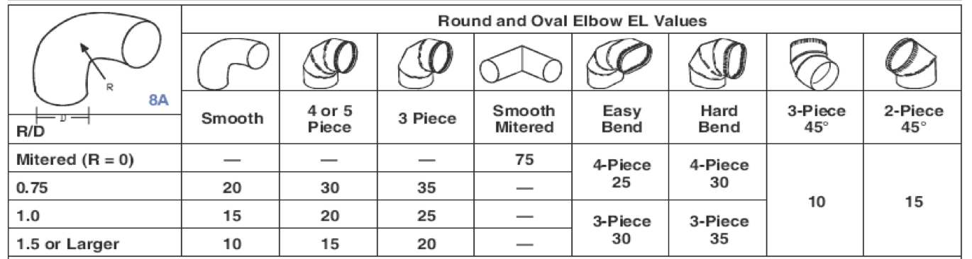
The main variables we have to work with for this fitting type are:
- Radius of the turn (R)
- Diameter of the duct (D)
- Number of pieces
- Round or oval
When we choose fittings, we pick them based on what’s commonly available at HVAC supply houses. We also go a little conservative here because we’re doing third party HVAC design and don’t have control over the installation. For example, most of the elbows used in actual duct systems have 4 or 5 pieces. We often choose a 3 piece elbow in our design, though, because it gives us a little slack in the design. If the installer uses the 4 or 5 piece elbow instead, with 5 feet less effective length, the actual duct system will be less restrictive than the designed duct system, at least in that part.
The total effective length (TEL) is the sum of all those fitting effective lengths plus the lengths of straight duct. If you’re doing it by hand, you have to go through the process for every single duct run. Then you choose the one that has the greatest total effective length. You do NOT use the sum of all the ducts and fittings.
Here’s a screenshot from RightSuite Universal showing the total effective length in one of our designs.
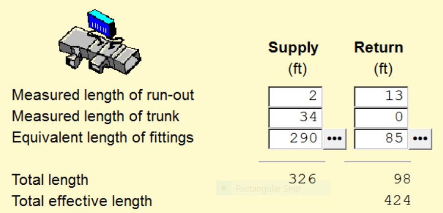
The lengths of straight sections of duct add up to 36 feet for the supply side and 13 feet for the return side. The fittings add up to 290 feet and 85 feet respectively. This is typical. Fittings dominate when it comes to using up the available static pressure, so you have to choose them carefully. Just take a look at that table of elbows above. If you choose well, you can be at 10 or 20 feet of effective length. If you choose that smooth mitered elbow, however, you end up with 75 feet.
The next step
Once you lay out your ducts and choose your fittings, you have a total effective length. But here’s a caveat: Those effective lengths for fittings depend on the velocity of the air, too, and it’s not a linear relationship. David Butler mentioned this in his comment below, and it deserves its own article in this series.
To summarize where we’re at now, let’s add the steps from today’s article:
- The blower creates a pressure rise to move air through the ducts.
- It’s rated for a certain amount of air flow at a specific total external static pressure.
- The ducts, fittings, and other components cause pressure drops.
- Subtracting the pressure drops for all the things that aren’t ducts or fittings from the total external static pressure yields the available static pressure.
- The available static pressure is the pressure drop budget you have to work with when designing the ducts.
- Each fitting has an effective length that equates its pressure drop to an equivalent amount of straight duct.
- When you add up the effective lengths of all the fittings and then add that number to the length of the straight sections in the most restrictive runs in the return and supply ducts, you find the total effective length (TEL).
The next step is to take your available static pressure and figure out what friction rate you have to work with in sizing the ducts. That’s next in this series.
Buy the ACCA Manuals on Amazon*


Other articles in the Duct Design series:
The Basic Principles of Duct Design, Part 1
Duct Design 2 — Available Static Pressure
Duct Design 4 — Calculating Friction Rate
Duct Design 5 — Sizing the Ducts
Related Articles
The 2 Primary Causes of Reduced Air Flow in Ducts
Don’t Kill Your Air Flow with This Flex Duct Disease
The Science of Sag – Flex Duct and Air Flow
The Secret to Moving Air Efficiently through Your Duct System
* These are Amazon Associate links. You pay the same price you would pay normally, but Energy Vanguard makes a small commission if you buy after using the link.
NOTE: Comments are moderated. Your comment will not appear below until approved.
This Post Has 11 Comments
Comments are closed.

Allison, I very much enjoy
Allison, I very much enjoy your articles here. You are covering topics it seems that up until lately no one wants to talk about. As a retired HVAC contractor, and now a national technical training instructor for WaterFurnace International, the determination of TEL and duct diagnostic static checks are probably the most misunderstood topics of design. I appreciate you taking this subject on and I refer the attendees of my classes to join and read your blogs. Thank you!
Thanks, Carl! We’ve done a
Thanks, Carl! We’ve done a few WaterFurnace designs.
Another informative article,
Another informative article, this time on a subject so fundamental, one would think there is little more to be said…but not in the hands of Allison Bailes!
You state the layout drawing above is “one we have done recently” and I must ask, are you referring to the drawing or has this system been installed and commissioned? I’m asking because it would be informative to know the outcome of your efforts, seeing no balancing dampers in the drawing. Optimistic, are we? 🙂
Overheard recently on NPR: A pessimist says “Things can’t possibly get worse.” An optimist says, “Yes they can!”
Good questions, Steve. I’d
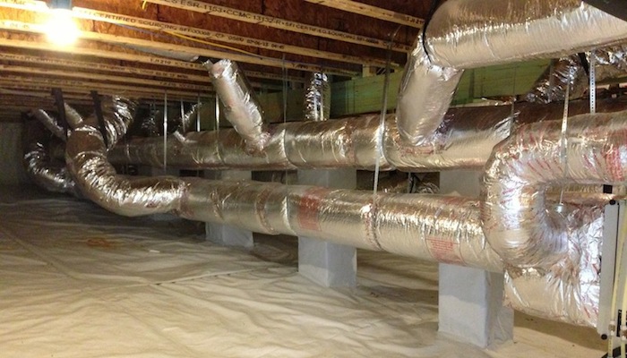
Good questions, Steve. I’d have to go back and see exactly which design that was from to know if it’s been installed or not. Sorry. I don’t recall. Also, the photo, duct schematic, and effective length table all are from different homes, and the photo isn’t from one that we designed. In the last article, Mark Johnson made the reasonable request for a case study so once I get through the basic principles here, I’ll do that.
Oops, one more query.
Oops, one more query.
I notice the main horizontal run in the layout ends not in 90* elbows, that with turning vanes would seem to be a better option, but at a termination that provides a short duct extension preceeded by a Tee.
What’s up with that?
Great question, Steve. That
Great question, Steve. That extension is there for very good reason. Yes, you could put an elbow there for the last takeoff, but it’s generally better for static pressure in the trunkline not to do that. And you don’t want to have the last takeoff right there at the end so you extend the trunk 6″ or so beyond the last takeoff. When air hits the end of the duct, it creates turbulence and you want to take the air off into the last branch before it hits the turbulence.
from the article… “Fittings
from the article… “Fittings dominate when it comes to using up the available static pressure, so you have to choose them carefully”
Absolutely true. However, most designers miss an important step when considering equivalent lengths of fittings (junctions, elbows, boots, etc). The values given in the Manual D Appendix 3 tables assume a velocity of 900 FPM and a friction rate of 0.08 IWC (700 / 0.08 for return fittings). However, this ignores the fact that fitting EL’s vary dramatically with velocity, and even if ducts are designed around those values (unnecessary and often a bad idea), velocities and friction rates will necessarily vary throughout the system, so you’re guaranteed to have the wrong EL’s in some or most cases.
Prior to 3rd Edition of Manual D, no one seemed concerned about this simplification. As long as you don’t exceed 900 FPM, the table EL’s are conservative.
In 2008, ACCA issued Technical Bulletin 2008-04, which goes into depth explaining what happens in a duct system when velocity is low, and why Manual D doesn’t stipulate minimum velocities (see my comment in part 2 of this series). This bulletin became Appendix 15 in the latest (3rd) edition of Manual D. Also found in 3rd edition is Appendix 4 “Fitting Equivalent Length Adjustments” (for when velocity and/or friction rate is lower than assumed for the Appendix 3 tables).
HVAC systems designed for homes built to current energy codes are likely to operate at significantly lower than 900 FPM, and as ECM blowers have become much more common, it’s even more important to adjust fitting EL’s for actual velocities as per Appendix 4. Unfortunately, popular duct design software** doesn’t implement these adjustments (although it would be rather trivial to do so). Sigh.
** I haven’t checked this is a while. I trust someone will correct me if any duct design software has implemented these adjustments.
Thanks for this important
Thanks for this important caveat, David. It’s worth its own article so I’ll add that to the list of articles in this series.
The total effective length
The total effective length (TEL) is the sum of all those fitting effective lengths plus the lengths of straight duct. If you’re doing it by hand, you have to go through the process for every single duct run. Then you choose the one that has the greatest total effective length. You do NOT use the sum of all the ducts and fittings. Is the computation for TEL is based on layout sir? . I cant find the length u used. Thanks for this article i learned soo much
Thanks for the primer on duct
Thanks for the primer on duct design! I am a novice about this subject and am living in an apartment with a very noisy intake grill in the door to a closet housing my HVAC blower. I think it is the air flow that is noisy, not the grill itself. Please say yea or neigh to what I plan to try to fix this problem: Install a 4 ft long rectangular partial enclosure (made with 1″ aluminum-covered foam insulation board) with end-openings the same area as the grill intake. The opposite end would take in room air 90 degrees to the original opening. Do you think this would compromise the safe air flow of my central air system? And Why or why not? Thanks in advance.
I read this post with great
I read this post with great interest Allison! Do you know of places where you can buy duct elbows with a radius of 1.5? The only places I’ve turned up so far seem to be more geared towards dust collection setups for shops (i.e. oneida-air.com and thesheetmetalkid.com), but I guess a duct is a duct at the end of the day, just seems odd the hvac supplies I’ve searched so far haven’t had anything like this.