Helping an Asthmatic HVAC System to Breathe
[This post was written by former EV employee Chris Laumer-Giddens.]
I live in a high-rise condominium in Midtown Atlanta. In an earlier post about this energy hog of a building, I focused on the huge heat loss conditions that exist, the missed opportunities to prevent these conditions through energy efficient design, and the high energy bills that we pay as a result of these missed opportunities.
Because it was the most affordable and practical, I immediately targeted the HVAC system. Specifically, I wanted to address the incredibly high static pressures and low air flow.
My first step was to invite our friend, Ken Briggs from Moncrief Heating and Air, to help me identify opportunities for improvement. 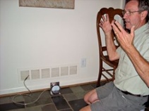 He ran the appropriate tests of the system (static pressure, air flow, etc.), and he also checked to make sure it was clean and performing properly.
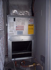
The first thing he pointed out was that the air handler was designed with a total external static pressure of 0.2 inches of water column (iwc). That static pressure is possible only with the low-resistance, stock fiberglass filter installed. The pleated, high efficiency filter that we were using was causing very high static pressure measurements in the system (0.6 between the filter and the coil), and reducing air flow in the duct system (both supply and return).
 He said that if the air flow were corrected, the system should not have to work as hard to bring the temperature in the condo up to the set point.
The challenge, or opportunity, as my former mentor would say, was to find a way to allow enough air flow without compromising air quality by using a standard filter. This challenge is made more difficult in our case because the fur from 2 cats and a dog can quickly overwhelm a filter.
The opening on the air handler was 16″x20″, and I considered a 6″ thick filter, with more surface area for air to pass through, but it still provided too much resistance. I needed a larger return air path.
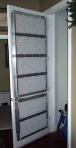 Solution: Move the filtration point from right in front of the air handler to the louvered door.
This does for our HVAC system what an inhaler does for someone with asthma – It opens up the airways and allows more air to flow. In our case, it does so by increasing the area of the restriction (the filters) from 320 square inches to 2100 square inches.
To accomplish this, I attached z-channels to the inside of the HVAC door closet to hold 6 pleated 14″x25″x1″ MERV 8 filters snuggly up against the the door over the louvered openings. Then, I sealed around the door with weatherstripping, and installed a threshold to seal up the 2-1/2″ undercut of the door.
To get a rough idea of the air flow, I stuck my hand and face 6″ in front of a supply register to gauge the difference in airflow between the modified door being open and closed (unfiltered open return path). As unscientific as this was, I felt little to no difference, which is what I was looking for. That means that the extra area of filtration allowed the air to flow as well as if there were no filters at all.
When I put a pleated MERV 8 filter in the intended location (right in front of the evaporator coil in the air handler), the air flow seemed half as much as with the filters on the door. In other words, by moving the filters to the louvered door, we doubled our air flow (at least to the extent that I could tell without a flow hood or other more accurate method).
Finally, I used a manometer to measure the static pressures in the system with the modified door. Recall that with the 320 square inch filter right in front of the evaporator coil, the static pressure was 0.6 iwc (0.9 with a dirty filter!). By opening that up to 2100 square inches of filters, the static pressure dropped to 0.23 iwc. That’s close enough to the 0.2 iwc design static pressure that I’m happy with it.
So, by modifying how we filter the air, we’ve essentially given our asthmatic HVAC system a set of healthy lungs! The static pressure across the air handler dropped, and it’s able to move a lot more air than before.
We’ve already noticed an effect on our energy bills, too. In November 2010, the electric bill was half of what it was in 2009. In December, which was colder than 2009 (and we used it more), the bill was 10% less. We’re really looking forward to the results in February/March 2011 because in 2010, we averaged $250 for those months.
Here’s to a prosperous and energy saving 2011!
This Post Has 10 Comments
Comments are closed.
Masterful response to the
Masterful response to the problem!
Great solution. Very creative
Great solution. Very creative!!
Are you certain the air
Are you certain the air handler is supposed to run at a maximum TESP of 0.2 in wc? It’s usually rated at 0.5. Normally, this info is on the air handler’s data label. However, I found a unit that told me its contribution to static pressure instead (o.15). When I looked at the installation manual, it said 0.5.
Congrats on the TESP reduction though! It sounds like everything is working at design specs.
Doc and Jamie, <
Doc and Jamie,
Thanks! We’re hopeful that it gives us the same kind of results in Feb/March and forever!
Sam,
Thanks for your question.
Yes, the air handler’s label does say 0.2, and this was confirmed by Moncrief tech, Ken Briggs, to be the case for this system. Because there is no heat exchanger, as is the case in a gas furnace, the TESP is lower. The heat exchanger adds more static pressure to the system, resulting in higher TESP (usually 0.5).
Chris, what a great (and
Chris, what a great (and creative) solution! Just make sure you keept that closet as clean as possible.
I can’t believe someone would install a system with such a low available static. Even with ‘normal’ systems, a thick media filter will choke the airflow. I usually spec the 1″ 3M Filtrete 1200, and if I know the return system is going to be tight, I specify grill filters, which provides much larger surface area.
Thanks David. We’ll make sure
Thanks David. We’ll make sure it shines like the top of the Chrysler building!
Unfortunately, mediocre systems and materials are par for the course in this building, except for the public areas, of course. I think the floor in our clubroom is Wenge wood!
Thanks for the tip on grill filters, good strategy for a tight system. I’ll have to consider my next design.
Chris,i assume you have
Chris,i assume you have insured there are no by-passes in the closet, like where the supply trunk penetrates the ceiling or drain line pipe-sleeve exits the building. These would be problematic in any case, but especially now. Otherwise, good idea.
What sort of equipment is it,
What sort of equipment is it, hydronic, heat pump, furnace?
Dan
Dan Oglesby, thanks for your
Dan Oglesby, thanks for your comment.
The supply trunk stays within the building envelope. From the top of the unit, it makes an immediate 90-degree turn in to the adjacent ceilings. There are no penetrations in to the floor or ceiling of the closet, only the walls for ductwork and hot water (HW tank sits below air handler)
Dan@balancepointhp.com:
The system is a split a/c with electric furnace. The condenser is in the garage.
The numbers continue to show
The numbers continue to show the success of this solution.
It was 17% colder* here in December 2010, than it was in 2009, but still our December 2010 electric bill was 22% less than 2009!
*This is result of comparing the Heating Degree Days (HDD) of December 2009 (702) with the HDD of December 2010 (823).