How to Read Manual J Load Calculation Reports
When you enter the world of building science — whether through building a house, becoming a home energy rater/building analyst, or just hanging out in cyberplaces like this — everyone talks about the importance of getting actual heating and cooling load calculations based on ACCA Manual J. A great number of HVAC contractors sell and install oversized equipment with air distribution systems that don’t work because these contractors base their choices on rules of thumb.
OK, but what if you hire a contractor or third-party designer to do Manual J load calculations and you’re not an expert and don’t want to be? Suddenly you’re faced with a bunch of seemingly indecipherable reports. How do you know if they’re accurate or not? Fear not, dear reader. I’ve got some help for you today.
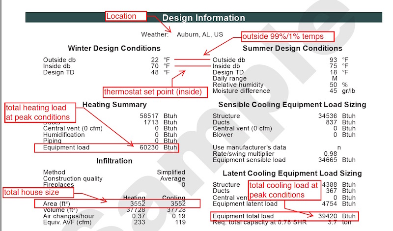
Don’t confuse load with capacity
I don’t think I can make this distinction often enough. Heating and cooling loads are not the same as the equipment capacity needed. I just did it in my last article, and now I’m doing it again. It’s that important. The first thing you need to know is that the term loads refers to how much heating and cooling the building needs and capacity refers to how much heating and cooling the equipment can supply. Here in the US, both are measure in British Thermal Units (BTU) per hour.
When you look at Manual J reports, you’ll see the loads. They’re shown separately for heating and cooling, and cooling is further divided into sensible and latent. When the contractor or designer picks a piece of equipment, they’ll have to go through a “derating” process to match the equipment’s performance specifications with the building’s loads. (For more on this, see What a Load Calculation Does NOT Tell You.)
I mention this topic here because some Manual J reports can confuse you on this distinction, especially for cooling. Depending on which reports you’re looking at, you may also see something like “Req. total capacity at 0.70 SHR,” as in the screenshot above. That’s just a guess at what equipment capacity you’ll need. If the person who ran the calculations has already gone through the derating procedure and specified the equipment, it may be accurate. Or the designer may have left the default number in there for SHR (sensible heat ratio), in which case you should look at that number simply as a suggestion.
In the end, just remember that the load calculation comes first, and your equipment capacity is going to be a bit bigger than the loads.
Notes on terminology
If you’re going to read Manual J reports, knowing a little about the terms used will help you understand them. Here are a few that you need to know:
- One ton of AC capacity is equal to 12,000 BTU/hr.
- BTUh is shorthand for BTU/hr.
- Sensible cooling results in lower temperature (technically, dry bulb temperature); latent cooling results in lower humidity through condensation of water vapor on the coil.
- SHR is the sensible heat ratio. It’s obtained by dividing the sensible cooling load by the total cooling load. For homes in eastern North America, the humid side of the continent, that number often comes in at 0.8 to 0.9, sometimes even a bit higher. In dry climates, it can be 1.0 when ventilating with outdoor air. Equipment usually comes rated an SHR of 0.7 or 0.75.
A rule of thumb you can use
I often rail against rules of thumb when it comes to HVAC design (or lack thereof), but that doesn’t mean you can’t use one to your advantage. This is the sniff test you can do to see how close the designer might have come to an accurate load calculation. In the warmer climates where air conditioning is a big deal, the rule of thumb used by many contractors for sizing an air conditioner is usually this:
AC capacity = CFA ÷ 500 sf/ton
CFA is conditioned floor area in square feet.
Sometimes the rule is 400 sf/ton, sometimes 600 sf/ton. But it’s always right in that neighborhood. So if you get a load calculation report, find the total cooling load (sensible plus latent) and divide it by the conditioned floor area. If it comes out around 500 or 600 sf/ton, the designer probably fudged the calculations somehow to align them with their preconceived idea of how big the loads should be based on their rule of thumb. (I’m talking about new homes here, or complete gut-rehabs. Existing homes generally have higher loads.)
Don’t believe me? Take a look at our data:
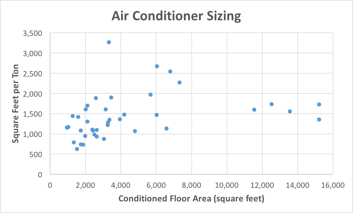
That graph is from an article I wrote in 2016 about the results of our load calculations on 40 projects. (Go read the article for full details.) The takeaways here are that our worst result was 624 sf/ton. The average 1,431 sf/ton.
If you’re building a well-insulated house with a good level of airtightness, double-pane low-e windows, and decent specifications overall — in other words, a house that meets most state energy codes these days — your result should be 1,000 sf/ton or higher. If it comes in lower that, you should see that as a red flag and delve into the details to see if the designer made mistakes.
Delving into the details
Finding the loads. First, identify the results for heating and cooling loads. The two main software tools for doing load calculations are Wrightsoft’s RightSuite Universal and Elite’s RHVAC. The reports look a little different but it’s not too hard to find the results. Both types of software make it clear how many BTU/hr you need for heating and for cooling. And for cooling, they also break it down into sensible, latent, and total. From the total cooling load, you can calculate the sf/ton I mentioned above. RightSuite doesn’t do it for you, but Elite’s software does. In the Project Report, they include a section called Check Figures that includes the sf/ton.
Checking the details. If you suspect that the loads may be too high — or too low or about right — you can check the details to see if the designer got the inputs right. Here are some of the main things to check:
- Indoor design temperatures. The standard indoor temperatures are 70° F for heating and 75° F for cooling (with 50% relative humidity).
- Outdoor design temperatures. The outdoor design temperatures depend on where you are, and you should check to see what was entered versus what should have been entered. It’s pretty easy to find the entries on the reports. To find what should have been entered, you can go to this page on the International Code Council’s website. If the entries in your calculation are off by a couple of degrees, it’s not a big deal. If they’re off by 5 degrees, you should ask for it to be corrected. (Read more about design temperatures here.)
- Areas. When the designer enters the various floors, walls, ceilings, windows, and doors, having the wrong areas can make a big difference. This is especially true for parts of the building enclosure that have worse specifications, like windows. A code-built house in IECC climate zone 3, for example, has windows that are about R-3 whereas the walls will be R-13. Entering too much window area is a way to inflate the load. Entering too much of any of the areas likewise inflates the load. It can be a lot of work to check all the areas, but if you suspect errors and can’t find them elsewhere, get out your calcuator and do it.
- R-values and U-values. Check the entries for the floors, walls, ceilings, and floors to ensure the designer put in the correct R-values (for insulation) and U-values (for assemblies, like windows).
- Number of occupants. A common way to inflate the cooling load is to add extra occupants. The rule here is that the number of occupants should equal the number of bedrooms plus one. If they put 23 people in a 5 bedroom house (Yes, I really saw that!), they’re adding unnecessary load. At 230 BTU/hr sensible and 200 BTU/hr latent, those 17 extra occupants added more than a half ton of cooling load.
- Infiltration. Did they use a simplified input method? If you’re building a new house and meeting a code that requires 7 air changes per hour at 50 Pascals (ACH50) or better, the entry should be “”tight” or maybe semi-tight.” Better would be to use an actual blower door number. For example, if your code requires 3 ACH50, enter that into the calculation. If you’re going for Passive House certification, enter 0.6 ACH50 or 0.05 cfm50/sf of enclosure.
- Orientation. The software gives the designer the option of using worst case for the orientation. Your load calculation should have the correct orientation or you’ll end up with extra load in your reports.
- Duct location. If the ducts are in conditioned space or in an encapsulated attic or crawl space, make sure that gets factored in properly. Doing the load calculations for ducts in an unconditioned attic will result in excess load.
Contractors doing these load calculations often feel compelled to stretch a little bit here and a little bit there. Each little bit doesn’t affect the overall load that much but by the time you add them all up, you’re looking at putting in a 4 ton air conditioner where 2.5 tons could work. But here’s the thing: Even when you’re as stingy as possible with things that add load, you still end up oversized by ten to fifteen percent. So there’s no need to add extra load. If you’re building or remodeling a high-performance house, make sure the load calculation is correct. It’s worth it.
Related Articles
What a Load Calculation Does NOT Tell You
Air Conditioner Sizing Rules of Thumb Must Die
The 3 Types of Heating and Cooling Loads
Got Manual J? Don’t Assume It’s Correct.
NOTE: Comments are moderated. Your comment will not appear below until approved.
This Post Has 25 Comments
Comments are closed.
Isn’t there a large
Isn’t there a large difference between the code required maximum infiltration at say 3ACH50 and the actual infiltration in a tight home not under the pressure influence of a blower fan? Seems that infiltration is another place where the calculated load can be fudged larger by a designer. In the example above there’s a 0.37ACH winter and a 0.19 ACH summer infiltration, what inputs influenced those numbers? Using 3ACH (if that was the code max) have a huge impact on the load.
Hi Lee, the code threshold
Hi Lee, the code threshold (3ACH50 in cold climates) is calculated directly from the blower door test at 50 Pascals and house volume. The air change rate shown on the above Manual J report is the estimated leakage rate at normal air pressure.
The software uses the Sherman-Grimsrud method (a series of formulas and look-up tables described in the ASHRAE Fundamentals Handbook) to convert from ACH50 to ACH-natural. In addition to the blower door result, the conversion depends on building height, temperature, winds, and proximity to nearby structures, all of which are input into the software.
Note that ACH-nat is typically different for heating than for cooling due to differences in the inputs, especially wind. Not to further complicate matters, but ACH-nat for the purposes of load calcs is different than the ACH-nat used for modeling annual energy loads. For the former, ACH-nat must be calculated using “design” conditions (temperature and wind speed), whereas with energy modeling, we use “average” conditions.
Thanks, Dave
Thanks, Dave
I’ve been doing commercial loads for 40 years, but am not familiar with the residential manual J calcs. Good to know there’s a conversion to the ACH-nat.
Assuming a average height of
Assuming a average height of 10′, 0.05cfm50/sq. ft. would seem to equate to 0.3 ACH50. Am I missing something?
The HVAC Contractor provided
The HVAC Contractor provided me with the Manuel J report for my new home. The home is 2,800 sq ft with a Equipment Total Load (Sen & Lat) of 26613 BTUH. Required Total Capacity at .70 SHR. The Total Cooling (Sensible & latent) is 34,000 BTUH. Live in Raleigh, NC – Outside DB 94 F, Inside DB 75, Design TD 19, Daily Range M, Relative Humidity 50 & Moisture Difference 44. Equipment Trane AHRI Ref 8819760. Efficiency 12.0 EER 14 SEER. What size cooling unit is needed. I appreciate any help!
@Michael, the Manual J load +
@Michael, the Manual J load + AHRI rated capacity is not sufficient to size the equipment, so it’s impossible to answer your question without further information.
A proper Manual S considers the sensible and latent capacity at the **design conditions** rather than at AHRI rated conditions. Manufacturers provide dealers with detailed capacity tables for this purpose. Unfortunately, many HVAC contractors don’t drill down to this level.
The system associated with the AHRI ref is nominally 3 tons. Based on the numbers you posted, that system will almost certainly have enough capacity to handle the load, but a 2-1/2 ton system might be more appropriate.
I would be interested in your
I would be interested in your opinion on the merits of use existing heating data rather than Manual J on sizing equipment for existing structures. I have extensive data on my HVAC system including power usage. Some professionals tell me this data is useless and the only way is Manual J. I don’t understand the rationale – maybe I’m missing something.
@Michael, “some professionals
@Michael, “some professionals” are simply wrong. For existing homes with properly functioning hvac equipment, “cycle timing” is by far the best method to estimate heating and cooling loads at a given temperature, assuming the equipment has sufficient capacity to handle the load.
You need to know the OUTPUT capacity of the equipment at the reference outdoor temperature, which is straightforward for a furnace since performance doesn’t depend on outdoor temp. OTOH, determining output capacity for compressor-based equipment is more involved as it requires the manufacturer’s expanded performance data. In the case of cooling loads, output capacity not only depends on indoor temperature but also on humidity (expressed as wet bulb) and airflow. No big deal for an HVAC professional.
When sizing a replacement system, I ask the client to provide cycle timing data, which I explain how to do. From that, I can determine the load (and thus size the replacement system) with greater accuracy than the most precise load calc.
With a furnace, cycle timing is simple enough that you can do it yourself. Take the average cycle ratio (on-time divided by total cycle time) over a couple of cycles ending around daybreak when the overnight low is as cold as you typically see. (For reasons I won’t bore you with, cycle timing should be done at a lower temperature than the standard design temperature for the location). It’s important that the indoor temp be stable during the hour or so prior to the beginning of a cycle timing session.
As an example, if you have a 80,000 BTUH 80% furnace, the output capacity is 64,000 BTUH. If it runs an average of 50% on the coldest morning, then the actual load at whatever the overnight low was on that day is 32,000 BTUH (64 x 0.5). Rather than waiting for extreme cold weather, you can cycle-time the furnace at 2 reference temperatures (say, 15F and 35F), which gives you the load curve. This can then be extrapolated to a lower temperature.
hi
hi
sir i am working on cooling load calculation but I have one problem that how I calculate heat flow rate of heater of a machine? please suggest formula.
We are looking at a ductless
We are looking at a ductless system for our church sanctuary and meeting room. The sanctuary is about 4400 ft.² with 20 foot ceiling peak in the meeting room is about 3200 Square feet also with a high peak ceiling. I’m not sure about the total volume due to the peak ceiling but I have calculated about 50,000 BTUs for the sanctuary in 28,000 for the meeting space.
There is a very low duty cycle, basically four hours on Sunday for the sanctuary and two or 32 hour sessions for the movie meeting area.
I am looking at two ductless systems With four fan modules in the sanctuary in one system with two with four fan modules in the sanctuary in one system with two fair modules and meeting area fan modules in the meeting area. These will all be wall-mounted at about 9 to 10 feet above the floor in both areas.
Is there any consideration for the peaked roofThese will all be wall-mounted at about 9 to 10 feet above the floor in both areas.
Is there any consideration for the peaked roof in these areas?
Thanks
@Jim, I think what you’re
@Jim, I think what you’re asking is whether you need to distribute air to the peak areas. The answer, in my opinion, is no. You need to distribute supply air to where the people are. You could use ceiling fans to mix the air, but natural stratification would actually save energy by reducing the delta-T across the ceiling-roof or ceiling-attic assembly.
Are you going with cassette type air handlers? In deciding how many, what size, and where to locate (including height above floor), you just need to make sure you get good coverage of the seating area. You’ll need to refer to the distribution diagram for the particular AHU model/size.
BTW, presumably the loads you mentioned (50k, 28k) are for cooling as opposed to heating? If so, be sure internal loads were included for a ‘full house’ in each space, as occupants typically drive the cooling load in a meeting hall. In heating mode, occupancy represents an internal gain, but it’s typically ignored since there may be circumstance when the spaces need to be heated for only a few people. Also, since a full house can create cooling loads even in cold weather, make sure the HVAC designer considers the minimum outdoor temperature the system is rated for in cooling mode. A low-ambient kit may be required, depending on envelope specs, climate zone and maximum occupancy.
Lastly, the ceiling-roof configuration has a pretty big impact on envelope load loads so you want to make sure that’s modeled properly. With volume ceilings, it makes a difference if the building has scissors trusses with a signficant attic space above, versus cathedral ceilings where rafters and joists are the same member. In the latter case, it makes a big difference if the roof is unvented, or vented above the insulation, and if so, how well (if at all) the ventilation channel is isolated from the insulation.
Thank you for this
Thank you for this information but I am still a little confused. My Manual J report states “4.93 Tons (Based On Sensible + Latent).” My sqft per ton number is 1,391 SqFt/ton. You indicated I would most likely need a little larger system than the load. The house has foam insulation. Would that be a 5 ton system? 5.5? 6?
@John, it’s a bit more
@John, it’s a bit more complicated than that. Manual J only establishes the design loads. Manual S covers equipment selection and design airflow. Air conditioning equipment should never be selected based on nameplate or AHRI rated capacity.
Manufacturers publish expanded performance data for each model-series showing the sensible and latent capacities at various indoor & outdoor conditions and airflow rates. From this, the designer can determine which model best matches the project’s sensible and latest loads at the project’s design conditions and target airflow. Most companies provide dealers with software or online tools for this.
BTW, given the size of your house (> 6,800 ft2 based on your question), even if a single system can handle the load, there are reasons why you don’t want to do that. All else being equal, larger systems (including multi-splits) are nearly always less efficient than smaller systems. But more importantly, the duct runs required to cover that much floor area would cause distribution issues. Whether or not 2 or 3 systems is warranted depends on your floor plan (layout) and room-by-room loads.
Whoever did your load calc can easily modify the model to divide the house into appropriate equipment zones and generate a room-by-room load report for each zone. Don’t be surprised if the total of the zone loads ends up being a bit larger than 4.93 tons. This is due to the loss of any diversity credit given to a single-system design (which would have been bogus anyway, given the size of the house).
If we know that MJ8 up-sizes
If we know that MJ8 up-sizes the heating and cooling loads by 20%, why manufacturers of equipment add more to the problem with the SHR at .7-.75?
Hi Armando, a system’s
Hi Armando, a system’s sensible heat ratio (SHR) depends on the relative size of the evaporator coil, evaporator airflow and entering wet bulb (absolute humidity of return air). The SEER rating procedure assumes 80F dry bulb / 67F wet bulb return air, which translates to a lower rated SHR than at typical operating conditions, especially in a dry climate. Moreover, the test procedure allows the manufacturer to decide what airflow each system is tested at.
Since manufacturers are more concerned with SEER ratings than sensible ratio, they generally test at lower than 400 CFM per ton, which increases both SEER rating and capacity, at the expense of SHR. That’s why the rated SHR is so low, and also why it’s important to select equipment based on actual rather than rated operating conditions!
Bottom line, the designer can dial in a lower SHR by selecting a larger evap coil combination and increase the CFM. However, it’s important to ensure the system has enough latent (moisture removal) capacity, keeping in mind that MJ is not the best predictor for latent loads.
Hi David – Thank you for the
Hi David – Thank you for the detailed explanation. A builder I designed a house for and I are trying to work with a new HVAC company. Its promising, but we have some small “difference” of opinion in couple a points. One is the SHR. My MJ8 calcs tells me I need a 2 ton heat pump for the 3000sf/HERS42/1ACH50 designed house.The HVAC guys want to install a 3 ton HP (16SEER, 10HSPF), since his numbers with lower SHR were at 2.4 tons. His explanation is that with variable speed units, it didn’t matter. I know to many folks that’s small potatoes, but when we’re trying to build an efficient zero energy house, every bit of load counts… btw, the calculated SHR from the loads is .90, so why use .70? That’s my argument!
Great question, Armando!
Great question, Armando! Naturally I can’t know how your mech contractor did the load without reviewing his reports, but I can tell you that the problem you describe is pervasive. As it turns out, MJ software requires the designer to stipulate system SHR so it can convert the sensible load to tons. This is WRONG as it ignores the Manual S procedure! Determining the size of the system is beyond the scope of MJ, thus in my opinion, the software shouldn’t need to know the equipment’s SHR, nor should it convert loads to ‘tons’.
In my experience, most contractors leave the SHR field at the default (0.75 in Right-J), probably because their MJ8 instructor didn’t correctly explain this setting. The problem is that (most) load calc programs were designed before Manual S was developed and before (most) manufacturers began publishing expanded performance data. But even if the designer determines the correct SHR and enters it into the MJ software, the resulting ‘tons’ shown on the report may still be incorrect. That’s because the software (at least in the case of Right-J) simply divides the sensible load by 12,000 to come up with tons. As explained in my previous reply, just because a system is rated 2 tons doesn’t mean it has 24,000 capacity at your design conditions.
For example, let’s assume the sensible load = 19,000, latent load = 2,000, and total load = 21,000, which is nominally 1.75 tons. A given 2-ton system might only have have 23,400 total capacity at your design conditions, which at first glance appears to be more than enough. Assume the expanded tables reveal a sensible ratio of .79 at your design conditions and design airflow. This works out to 18,486 sensible, not enough to satisfy the load!
As noted in my previous reply, the designer can select a different coil and airflow setting and perhaps satsify the load… But keep in mind, it may be counterproductive to try to match the load’s SHR (90% in your example, not unusual in the Southwest). In any case, there’s nearly always a difference between the load SHR and the equipment SHR.
Bottom line: I would not rule out that you may actually need a 2.5 ton system, but if the contractor set SHR = 0.7, my guess is that he’s simply using the SHR as a ‘fudge factor’ rather than following the Manual S procedure.
Sorry, next-to-last sentence
Sorry, next-to-last sentence in my initial reply should read: “…dial in a higher SHR…”
David – Thank for helping me
David – Thank for helping me understand this issue, I really appreciate it. I got my marching orders, ;-))
The only thing better is if
The only thing better is if your documents were in complete PDF downloads.
Hi we just got done building
Hi we just got done building a home and the HVAC company used the wrightsoft program to size our unit and it is not performing at all. We feel it was grossly undersized! The unit is running non stop and does the same cycle each day. Wake up and it’s maintaining the set temperature and as the day progresses it gets higher and higher then what the thermostat is set at. And then runs till about 2 am to get it back down. Then repeat. They provided me w the report and there are a lot of numbers manually overridden. It’s area is 4555 sq ft and they put in a 3 ton unit. Can you please give any input?
@Heidi, it’s impossible to
@Heidi, it’s impossible to know what went wrong without auditing the load report, coupled with on-site assessments and diagnostics. But I can make the following observations:
1) manual overrides in the load calc software aren’t necessarily a bad thing
2) inability to satisfy the load could be caused by equipment problems and/or installation issues
3) critical construction details may not have been nailed down prior to hvac rough-in, or may have changed after rough-in
4) the HVAC contractor may not have done a proper Manual S calculation (equipment selection) based on the load report
5) even if 3 tons is enough capacity on paper, 4500+ ft2 seems too large to me for a single system (may be impossible to balance)
Bottom line: Proper design and installation involves a lot more than getting the load correct.
What does the HVAC company say about the problem? At a minimum, they should install a data logger (e.g., HOBO) at the thermostat location to document the temperature performance. With that, it should be obvious there’s a problem. If they ultimately agree to replace the AC, you should have an independent designer review their plan. For example, the furnace or air handler may also need to be replaced in order to get sufficient blower capacity. Also, as I said, I’m skeptical that a single system can handle a house that large.
Hi David, thank you for the
Hi David, thank you for the educational information. I have new home construction and have been in discussion with the builder and HVAC trade for over a year that the Rh isn’t managed well with the cooling system. I have a copy of the Wrightsoft load report at 128 pages long. This article mentions that a simplified check can be made by taking the Total Cooling Load and dividing it by the CFA, 34,048(Btuh) / 2,860 (sf) = 11.9. I’m expecting a more significant value, i.e. 400sf, 500sf, 600sf, not 11.9. What have I fat thumbed?
-thank you
SS, you’re close but you
SS, you’re close but you missed two things in your calculation. What you’re trying to end up with is square feet per ton, so you have to do the division the other way around. Before that, though, you need to convert BTU/hr to tons.
34,048 BTU/hr ÷ 12,000 BTU/hr / ton = 2.84 tons
2,860 sf ÷ 2.84 tons = 1,008 sf/ton
@SS, when you say RH isn’t
@SS, when you say RH isn’t managed well, I assume you mean it sometimes gets too high. To address this issue, it’s important to first identify the moisture source(s) and verify the cooling system has adequate latent capacity (i.e., moisture removal capacity).
Common sources include excess ventilation air and/or infiltration, inadequate spot exhaust for showers & cooking, and poor roof and/or site drainage. Excess moisture in an vented crawl space or unconditioned basement will migrate into the home through leakage paths in the floor. And if the air handler and/or ducts are located in unconditioned space (including attic), any return-side leaks will draw in ambient moisture and overwhelm your A/C’s latent capacity. Home performance professionals rely on various diagnostic tools and methods to identify the sources for the moisture in your home.
Not knowing anything about your home or where you live, 1000 ft2 per ton suggests your RH issue is probably not the result of gross oversizing. But even a properly sized A/C can fall short on moisture removal if not set up properly. For example, continuous fan (as opposed to “auto”) tends to re-evaporate residual moisture on the coil at the end of each cycle. And the A/C’s latent capacity will be compromised if airflow is set too high or coil is too large for the condenser (requires independent evaluation by a qualified HVAC tech).
Supplemental dehumidification should only be considered as a last resort, after all sources of moisture have been minimized to the extent possible (‘source control’), and A/C latent performance optimized.