Converting Heating and Cooling Loads to Air Flow – The Physics
When you embark on the project of educating yourself about building science, one of the first things you encounter is the concept of heating and cooling loads. Every building has them. (Yes, even Passive House projects.) That’s why we do heating and cooling load calculations. We enter all the details of the building, set the design conditions, and get the heating and cooling loads for each room in the building. Here in the US we still use those antiquated units that yield British Thermal Units per hour (BTU/hr) for the loads. In most of the world, the result is measured in watts of kilowatts.
But then what? We don’t just turn on the BTU spigot. We typically move those BTUs into and out of the rooms in a house with a fluid, like air or water. So how do we know how many cubic feet per minute (cfm) of air will give us the right number of BTUs per hour? Today we’re going to talk about this relationship between BTU/hr and cfm. (I’m going to leave the discussion of using water for heat distribution to my friends on the hydronic side, but it’s analogous to what I’m explaining below.)
Before we get started, let me note that there’s a little bit of math ahead. It’s really not that bad, and if you can follow along, you’ll have a better understanding of the physics behind moving heat with air. If you’re already hyperventilating after seeing the word “math,” you can skip down to the takeaways section.
How much heat can air hold?
Matter is pretty neat stuff. It has all kinds of interesting properties that have kept scientists hidden away in laboratories for centuries. (I hear that Galileo is still toiling away in the basement of the Leaning Tower of Pisa.) When talking about the capacity of air to hold heat, the relevant property is called — you’re not gonna believe it — heat capacity. Yep. It’s a term I’ve mentioned occasionally in this space but never really defined, so let’s take care of that today.
Heat capacity is kind of like efficiency. It’s a bang-to-buck ratio. With efficiency, the equation is output over input. With heat capacity, it’s a ratio of the heat added or removed to the temperature change. Here’s the equation:

If we add a certain amount of heat (measured in BTUs) to a certain amount of matter (air, in our case), we’ll get a certain amount of temperature change. What this equation tells us is that the ratio of those two quantities is a measure of how much heat a substance can hold. If we get half as much temperature change for a given amount of heat added, that material has twice the heat capacity. So this quantity, heat capacity, is an important property of materials for anyone interested in energy efficiency or heating and cooling.
It’s usually easier to talk about specific heat capacity because the Q in the equation above will change with different amounts of air, the substance of interest here. By dividing the right side of the equation above by the mass of air, we get the specific heat capacity. If we rearrange a little using the magic of algebra, we get an equation you may recall from high school or college. (It shows up in introductory classes of both physics and chemistry.) Here it is:

Look familiar? If not, hang with me just a little longer and I’ll show you an equation you may have seen before.
The next step is doing a little conversion for the mass term. When we deal with fluids, it’s usually easier to work with density, which equals mass divided by volume. So we replace the m term above with density (Greek letter rho, ρ) times volume (V). Here’s what our equation looks like now:

Whether the math is causing you to hyperventilate or not, let’s step back a second and recall where we’re going here. The original question was about how we take heating and cooling loads in BTU/hr and determine how much air flow we need in cfm. We’ve got a term in the equation now for volume and cfm is just volume over time. One of the great things about algebra is that we can divide (or multiply) both sides of an equation by the same thing. In fact, it’s encouraged!
So let’s divide both sides of the above equation by time. On the left, we end up with Q/t, which gets us to the BTU/hr we’ve been discussing. On the right, the volume, V, divided by time gives us cubic feet per minute. Of course, to end up with BTU per hour on one side and cubic feet per minute on the other, we need to throw in a factor of 60. It goes on the right side.
Also on the right side, we have ρc, the density of air times the specific heat of air (at constant pressure, but that’s another discussion). Density and specific heat are just two numbers we can multiply, and just to be clear, we’re talking about air at sea level and near room temperature. You can’t use the equation below up high in the mountains or at temperatures far from the air you’re breathing right now. When we multiply density (0.075) by specific heat (0.24) and also by 60, we get 1.08. The final equation looks like this:

This is the equation I said you may have seen before. It’s taught in HVAC programs and BPI classes as well as other places. If we rearrange this equation to get air flow on the left, we end up with:

And there we have it. Once we know how much heat a room needs to have supplied or removed, we can do a simple calculation to see how many cubic feet per minute of air flow we need. Of course, the cfm we need will depend on the location. You can’t just use 1.08 everywhere, as I said above. And we also need to know how much the temperature of the air changes when it goes through the furnace or air handler, the ΔT in the equations above.
Is that all?
I know what some of you are thinking now. You’re looking at all that I’ve done above and you’re saying to yourself, that’s sensible. And you’re absolutely right. The equations above are only for the sensible heat added to or removed from air. It doesn’t include the latent heat part of air conditioning, the part that deals with moisture removal.
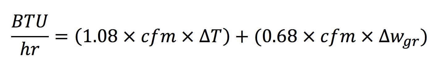
We could go back to the beginning and go through a similar process for the latent heat removal. Heck, we could go even further back and talk about the partial derivative of enthalpy with respect to temperature. But how about I spare you those details and give you the answer right up front. Here’s the analogous equation for the total heat (sensible plus latent):
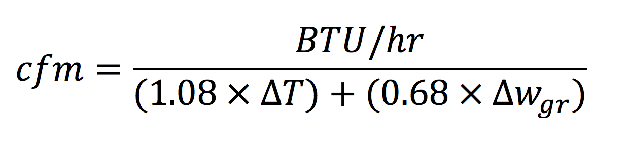
Doing a little algebra magic again, we get the equation for cooling cfm:
The only thing new here is the Δw variable. That represents the change in humidity ratio, and the gr subscript is for grains. Humidity ratio (often mistakenly called absolute humidity) is one of the main variables on a psychrometric chart and is measured in grains of water vapor per pound of dry air. The grain is a weird way of talking about the mass of water vapor, with one pound (mass) of air being equivalent to 7,000 grains.
Basically, Δw measures the change in the amount of water vapor in the air moving through the air conditioner when some of it condenses on the cold evaporator coil. When air passes over a cold evaporator coil, two things happen. The air temperature drops (ΔT) and the concentration of water vapor in the air also drops (Δw) as the water vapor condenses on the coil. Both of those changes are part of the cooling capacity of a piece of equipment.
The takeaways
If you got lost in the math up above and jumped down here, let me see if I can summarize things a bit for you. I started by looking at the physics involved in air flow and heat. That was all based on the definition of heat capacity, which is a measure of how much temperature change you get in a material for a given amount of heat added or removed. That resulted in the pair of equations that relate the three variables, BTU/hr, cfm, and ΔT. There’s a number (1.08) in the equation, too, and although it looks like a constant, it’s not. You have to remember to adjust it if the density of air isn’t the same as air at sea level near room temperature. (The heat capacity can vary, too, but for what we’re doing here, it’s mainly the density you have to adjust.)
Then I showed that those two equations are only for sensible heat; that is, the heat that causes temperature changes. If you have moist air (and who doesn’t want that!) and are cooling it, you also have to consider the heat involved in removing water vapor from the air stream by condensing it on the cold air conditioner coil. That led us to the second pair of equations, which includes that heat, the latent heat.
If we had to start from first principles and do all the physics every time we design a heating and air conditioning system, we’d probably just be sitting around the fire in winter or fanning ourselves with palmetto leaves in summer. Instead, we have procedures for taking load calculation results and getting the right piece of equipment that moves the right amount of air with the right number of BTUs. That’s the engineering side.
So, you have the answer to the original question. We know how to go from a BTU/hr heating or cooling load to the cfm of air flow needed to meet the load. The heart of it is pure physics. The design process is engineering, and that’s the topic of a future article.
Related Articles
3 Reasons Your 3 Ton Air Conditioner Isn’t Really 3 Tons
Psychrometrics – Impenetrable Chart or Path to Understanding?
The Magic of Cold, Part 2 – Intermediate Air Conditioning Principles
NOTE: Comments are moderated. Your comment will not appear below until approved.
This Post Has 33 Comments
Comments are closed.
I agree that I-P (inch-pound)
I agree that I-P (inch-pound) units (formerly known as English units) are a pain, but they quite common in the U.S. However, I don’t think that “grains” are considered to be I-P units. ASHRAE tables and psych charts in I-P units express humidity ratio as pounds of water per pound of dry air, so be careful in using the above equation with ASHRAE and some other I-P charts and tables. I consider “grains” to old-timer units of measure, and I am no spring chicken.
The math does not bother me,
The math does not bother me, but all those Greek symbols drive me to distraction. I always wondered how much more understandable the subject would be if we replaced all the Greek with 1-10 character abbreviations, the way it would be in a modern computer language. Am I the only one?
Mark,
Mark,
Those Greek letters are what make physics so beautiful! What drives me to distraction is the way engineers write equations with silly variable names like nMEUL. (It stands for normalized modified end use loads and is used by RESNET.)
I like greek characters and
I like greek characters and letters with subscripts for variables. I hate it when people use the unit names (cfm, rpm, Btu, etc.) for variable names.
I’m in total agreement with
I’m in total agreement with you there, Roy. I had to look away when I typed those equations above because it’s so offensive to me to use unit names for variables. But I did it anyway. Maybe I shouldn’t have, but I think some readers here are used to seeing them that way.
Here is a common conversation
Here is a common conversation that I have when working with “real” engineers:
Real Engineer: What are the expected cfms and watts for that fan test?
Engineering Snob (Me): Do you mean air flow rate and power?
Real Engineer: Yea, the cfms and watts.
Me: I don’t know. It depends on the Fahrenheit’s of the air?
And I wonder why people quit coming to me for help . . .
You sound you like you should
You sound you like you should have been a physicist, Roy!
It gets even worse. We were
It gets even worse. We were doing vibration testing on an outdoor unit. I asked the engineer for the natural frequency that was measured during the test. He said it was about half a “hert” (singular for Hertz?). Then I asked him for the fan speed. He said 1100 rpms (revolution per minutes?).
RoyC,
RoyC,
Yeah, I suppose you’d have to be careful if you were looking something up in a table. But who does that anymore? We live in the age of apps. I recall having to look up enthalpies in steam tables in my undergrad thermodynamics class and it wasn’t fun.
Allison, if you don’t get
Allison, if you don’t get humidity ratios from tables or psych charts for use in the above equations, where do you get them? Are you going to derive air property equations next? As for steam tables, the worst part was when you had to double-interpolate for superheated steam properties.
Nerdy stuff well dine as
Nerdy stuff well dine as usual. Nice work Alison. I always like to be able to show people that in fact you can calculate the required airflow instead of guessing!? And adding 50% won’t “fix” the math you don’t believe in.
What!? No safety factors! Who
What!? No safety factors! Who could live in such a world, Geoff!
I’m glad you noted that air
I’m glad you noted that air density (0.075 lb/cu ft (1.204 kg/m3) is for Normal Temperature and Pressure conditions
– 20 C (68 F)
– 1 atm (101.325 kPa, 14.7 psia, 0 psig, 29.92 in Hg, 407 in H2O, 760 torr).
This factor is often overlooked and leads to error.
Or is it air-or?
In a previous job I was
In a previous job I was responsible for the psychrometric equations implemented in a family of HVAC diagnostic tools. I recall struggling for weeks to reconcile routine calibration measurements with theoretical mole-based moist-air equations from ASHRAE Fundamentals. The intruments were measuring the change in enthalpy across an air handler with a refrigerant coil. (CFM, delta-T, delta-W).
Then it hit me. Our instrument cluster measured the barometric pressure as a baseline correction for “Normal” atmosphere, but we only took one pressure measurement and adjusted everything to that. I was amazed to discover that it’s necessary to account for the delta-P between measurement points, i.e., at each end of the air handler!
Yup, the change in air density imposed by the blower fan affected the measurements enough that our reference instruments appeared to be out-of-calibration, even though they were spot-on. It was my equation for supply-side enthalpy that was wrong since it referenced the same pressure as my return side equation!
David, could you share some
David, could you share some more details on these calculations? We are always careful to correct for barometric pressure, especially due to elevation. I am at about 1000 ft of elevation which means that barometric pressure is about 14.2 psia compared to 14.7 psia at sea level, under “average” weather conditions. This results in about a 4% density difference. However, when looking at coil pressure drops or blower pressure rises, we are usually only talking about 1 in.w.c. or less which is about 0.04 psi of pressure change. This results in about a 0.3% change in density. Is your instrumentation that accurate?
@Roy, I was talking about the
@Roy, I was talking about the reference instruments we used to calibrate the field instruments, not the field instruments themselves. Granted, the pressure drop across an AHU had no practical impact on field measurements, as the effect I described is well within the margin of error. And there was never any discussion of adding a pressure sensor to our supply side probe! This was simply an effort on my part to understand what was going on.
The biggest problem you run into when trying to measure air conditioner performance in this manner is error stacking — each instrument (temp, RH, pressure & airflow) introduces error into the BTU calculation, which becomes additive. RH and airflow are the main culprits as they cannot be measured with the same precision as pressure and temperature. In order to get useful BTU calculations, you have to do everything possible to avoid introducing unnecessary errors into the procedure.
In teaching psychrometric air
In teaching psychrometric air side equations to HVAC (often first year) students I use dimensional analysis (cancelling like terms) to show what is contained in the “4.5”, “1.08”, and “0.68” variables, as I remember when I was a student, these variables were not broken down by analysis as much as I later learned how to do it:
4.5 = (ft^3/1 minute) * (delta BTU/1 lb. of air) * (60 minutes/1 hour) * (1 lb. of air/13.35 ft^3)
Above, the ft^3, minute, and lb. of air terms cancel, leaving 60/13.35, which equals 4.45, which is then rounded to 4.5.
My goal in demonstrating this to students is so they can see what all is contained in that “4.5” vs. “You gotta use it just because it’s how you do it to get the BTU you want to find…”, as an answer to the student who asks (and the one or two who ask are always the ones I mentally note are showing curiosity and also tend to do better throughout the course) “What does that 4.5 mean anyway?” By looking at all of the terms contained in the dimensional analysis process, one can see that “4.5” is derived from air density, time, volume, weight, and heat content. One could plug all the variables in, leaving the above analysis intact, and derive the same result as:
4.5 * CFM * delta E = BTUH
But, as Allison said above, if we had to do that each time we’d likely still be sitting by open fires for warmth and fanning ourselves with palm leaves for cooling.
Just wondering if you have
Just wondering if you have any Greek equations for: 2 adults 3 kids and 1 dog opening and closing the doors, exact placement for thermostat on open concept floor plan, how much airflow changes as the filter gets loaded, what to do for a party of 25-30 guests in the middle of summer? Furthermore can you help me calculate how much heat gain there is on the second floor of a two system layout? And also can you tell me how much cooling is lost from the upstairs system over the Balcony?
Are the above equasions only
Are the above equasions only for cfm to btu calculation through cooling or heating equipment? May I also use them to prove/disprove proper cooling supply to a room? Say I add the wattage of the room add the two boddies heat load and come up with 4000 btu/h of cooling needed to remove this load. I know the formula BTU/H=1.08xCFMxDt is for specific heat and that BTU/H=4.5xCFMxDe for cooling load. So my quesion is if I use a flow hood and measure 200 cfm at 55deg SA and a room RA of 78 can I use this delta T in the equation or must I measure at the equipment return? I realize for cooling i will have to use delta E but the question is the same.
What should the cooling
What should the cooling airflow to the living room be if the total cooling load of a home is 29,500 BTUs/hr, and the cooling load for the living room is 4,425 BTUs/hr with a total cooling airflow of 1,082 cfm?
@Loc, it would be reasonable
@Loc, it would be reasonable to apportion the system airflow based on the load ratios. In your example, the living room represents 15% of the load, so the airflow to that room should be close to 15% of system airflow, or 162 CFM.
How to calculate the needed
How to calculate the needed airflow to cool a chamber with a volume of 65 m3 from 450C to 80C in one hour
Thanks for the help
Rui
@Rui, not enough information.
@Rui, not enough information. In particular, the specific heat and density of the air contained in the chamber depends on its pressure. Building load calculations assume ‘standard atmosphere’ values as noted in Allison’s article. These assumptions won’t work in what appears to be the industrial application you describe.
Moreover, assuming we’re not talking about a hermetically sealed chamber (in which case you wouldn’t be able to used forced air cooling equipment), the atmospheric pressure in the chamber will naturally drop as the air is cooled, so simple heat transfer equations won’t work.
Finally, more context is needed for this type of calculation. For example, has the heat source that created 450C air ended? What are the ambient conditions for the condenser and for the chamber? Would a fluid-based cooling system be more appropriate? In any case, this is not the appropriate forum to address the application you describe.
great and simplified
great and simplified explanation.
a question:
considering we have a two HVAC units (same model) working on the same conditions (the same ambient temperature/same on-coil temperature).
with only one difference, the CFM not same for both machine.
does the total capacity change or would be the same for both HVAC units?
Mohamamd, yes, the capacity
Mohamamd, yes, the capacity would be different if the air flow is different. If you look up the expanded performance data for your system, it will show how the capacity changes with air flow rate, temperature (indoor and outdoor), and humidity. In addition to changing the total capacity, changing the air flow also affects the balance of sensible and latent capacities.
Expanding on Allison’s
Expanding on Allison’s comment, system airflow has a MUCH larger impact on sensible (and latent) capacity than total capacity. For example, referring to a Carrier 3-ton heat pump at 1200 CFM (400 CFM/ton, nominal), 63 entering wet bulb (75F dry bulb @ 50% RH) and 95F outdoor:
If airflow drops to 1050 CFM (350 CFM/ton), total capacity will drop by 2.1%, whereas sensible capacity will drop by 6.5% and latent capacity will increase by 18.5%! OTOH, if airflow increases to 1350 CFM (450 CFM/ton), total capacity will increase by 1.7%, whereas sensible capacity will increase by 6.2% and latent capacity will decreases by 19.6%!
Interestingly, rated kW input changes less 1.5% either way. This is why getting the airflow correct is so important. So, what is the correct airflow? It depends on how much latent capacity is needed. As we can see, dehumidification is a direct trade-off for sensible capacity and efficiency. In residential practice, designing a system to operate at less than 50% RH – ostensibly for improved comfort – is wasted energy in my opinion. But that’s another conversation.
thank you David and Allison.
thank you David and Allison.
i got your point, changing one parameter in the system will change all others and you can’t assume things will keep constant.
taking the numbers in your reply “”””Carrier 3-ton heat pump at 1200 CFM (400 CFM/ton, nominal), 63 entering wet bulb (75F dry bulb @ 50% RH) and 95F outdoor:
If airflow drops to 1050 CFM (350 CFM/ton), total capacity will drop by 2.1%, whereas sensible capacity will drop by 6.5% and latent capacity will increase by 18.5%! OTOH, if airflow increases to 1350 CFM (450 CFM/ton), total capacity will increase by 1.7%, whereas sensible capacity will increase by 6.2% and latent capacity will decreases by 19.6%!””””
1- what the reason behind the total capacity change? from engineering point view?
2- how you find and calculate the % of increases and decreases?
@Mohamamd, mass-flow
@Mohamamd, mass-flow properties determine how much heat is transferred between air and refrigerant. Essentially what happens is the more air (mass) you move across the coil, the warmer the coil becomes, thus increasing the delta-T between air and refrigerant. This allows more heat to be transferred. At first it seems counter-intuitive since the supply air is warmer, but the additional volume of air moved across the coil more than makes up for that. If you graph airflow vs total capacity at a given set of operating conditions, you’ll see the relationship is non-linear.
BTW, the same principal applies to heat pumps in heat mode except in that case, the exchange that occurs at the indoor coil is sensible heat only.
I derived the % increases/decreases from the expanded performance data for the Carrier 25HPB636-30 heat pump. See the table on page 13 of the Product Data PDF: https://www.carrier.com/residential/en/us/products/heat-pumps/25hpb6/ (scroll down to Documents section and select docs for Engineers, Architects and Contractors, then scroll down to Product Data).
I want to remove moisture by
I want to remove moisture by cooling 3000 cfm of air from 95% deg.F at 95 RH down to 39 deg.F at 39 RH. If I understand correctly I would calculate btu/hr = (1.08 * 3,000 cfm * 56 Dt) + (.68 * 3.000 cfm * 256 Wgr) = 181,440 btu + 522,240 = 703,680 btu/hr of cooling capacit.
thanks again, i am keeping
thanks again, i am keeping this article as a reference for me, and always i refer back to it to help me in solving some issues.
we have two capacity element in the cooling BTU/h: sensible heat and latent heat.
the “Power input (KW)” to the HVAC unit (lets say RTU) are drawn by the unit to run the fan/compressor/other accessories.
as we know the conversion between Btu/h to KW ===> btu/h = 3.412 * KW (“conversion formula”)
the question:
the KW in the “conversion formula” is the same KW the “input power”
There would be no reason to
There would be no reason to convert “input power” (KW) to BTU/H. The KW-BTU/H conversion formula is useful for converting “output power” from KW to BTU/H or vice versa. When we specify or measure an air conditioner’s output in BTU/H, we can calculate the EER (energy efficiency ratio) by dividing BTU/H output by KW input at a given operating point. OR, we can calculate COP (coefficient of performance) by dividing KW output by KW input. Hence, we can convert EER to COP by the following formula: COP = EER / 3.412.
thanks David
thanks David
yes, what was of common understanding to me. converting between the output power into different units of measure (BTU/h, or KW, or TON). but i have seen a YouTube video using the input power and convert it into BTU/h to eventully calculate the CFM using the sensible cooling formula (https://www.youtube.com/watch?v=aRJH-wJZ1Gs&feature=youtu.be)
i thought in beginning that would wrong,
1- what you think in the used formula?
2- how we can use the input power to calculate the output cooling power? (eventually after all, the input power was consumed in fever of producing only cooling output)
3- COP = output KW / input KW, and COP value always higher than 1 (ranging in 3 COP for most of the time), how can an output power be higher than input power?
1. The formula described in
1. The formula described in the video is for sensible heat. If you apply that to air conditioning as you suggest, you’d be ignoring latent capacity and therefore CFM would be incorrect (understated). You would need to also measure the change in latent heat (delta-humidity ratio) across the evaporator coil. In practice, this could be done with a precision relative humidity probe and then convert the result to absolute humidity. Formulas for that can be found here: https://www.engineeringtoolbox.com/cooling-heating-equations-d_747.html
Keep in mind, it’s very difficult to measure cooling CFM in-situ (either directly or indirectly) with precision any better than about 10%, due to sensor error stacking.
2. It is impossible to use input power to calculate cooling output power. In particular, cooling COP varies significantly with conditions. If you were to back into output power using input power x rated COP, the result would only be ‘correct’ if site conditions exactly match rated conditions. In the test scenario from the video, this isn’t a problem since the test involves electric resistance heat, which by definition has a COP of exactly 1.
3. Compressor-based air conditioners (and heat pumps) have a COP greater than 1 because of the ‘magic’ of the refrigeration cycle. This requires more than a few words to explain… I believe Allison wrote an article about this?