Duct Design 2 — Available Static Pressure
In part 1 of this duct design series, I discussed the basic physics of moving air in ducts. Now we’re going to take that and use it to figure out how to make all the parts work together properly. First we choose a blower that will give us the total air flow we need. Then we design a duct system that will deliver the proper amount of air to each room. To do that, we need to take the concept of pressure drops and apply it to blowers and ducts.
More about pressure drops
We know from part 1 of this series that there will be pressure drops all through the duct system. Whenever air encounters a filter, coil, heat exchanger (if there’s a furnace), registers, grilles, balancing dampers, and the ducts themselves, it loses pressure. So let’s sort this out.
The diagram below shows the components of our system. The AHU is the air handler (or handling) unit. That’s where the blower is. Air inside the home gets pulled back to the AHU through the return ducts. The air gets conditioned inside the AHU and then sent back into the home through the supply ducts.
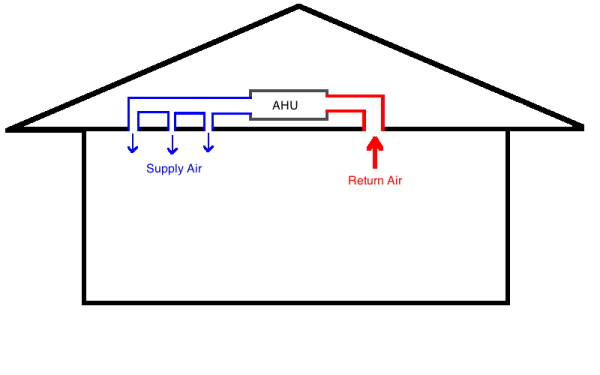
When talking about pressures here, we’re not talking about absolute pressure. We’re talking about relative pressure. Our reference when we talk about pressures is the pressure inside the conditioned space. That’s our zero.
On the return side of the blower, the pressure will be negative. As the air moves from the room, into the return grille, and down to the AHU, the pressure gets more and more negative relative to the room. On the supply side, the pressure is positive. As air moves from the AHU through the supply ducts and out into the rooms, the pressure gets less and less positive.
The maximum positive and negative pressures occur at the air handler. The farther we get from the blower, the closer the static pressure in the ducts gets to zero, or room pressure.
Blower capacity
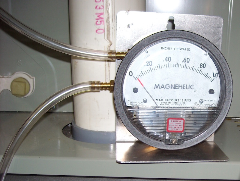
To get a certain amount of air flow, a blower needs to operate against a certain pressure and at a certain blower speed setting. Here’s a table from one unit.

The blower speed is set by moving wires to different taps. In this case, there are 5 of them. The row of numbers across the top is the total external static pressure (TESP) the AHU is rated for. That’s the pressure change across the AHU when pushing and pulling air through the ducts.
You generally want to design a system to operate on medium speed (tap 3 in the table above). That way you have some room for adjustment when you commission the system. Also, most systems are rated to operate at an total external static pressure of 0.50 inches of water column (iwc). For the system above, those parameters yield an air flow of 899 cfm. If that’s the number you need, you just have to make sure you design your system to operate at 0.5 iwc.
So, from the return (most negative) side of the AHU to the supply (most positive), we want a total pressure change of no more than 0.5 iwc. (That’s the typical number. Some air handlers are rated higher. Some are rated lower.) That’s the total pressure change across the AHU. The actual pressure in the system will depend on the ducts and other components. As long as we’re at or below 0.5 iwc in this case, we’ll get good air flow.
Notice I said pressure change here, not pressure drop. The blower causes a pressure rise. It’s the force behind the air flow so from the negative side (return ducts) to the positive side (supply ducts), the pressure rises.
Got all that?
Finding the available static pressure (ASP)
What happens next is splitting up the two kinds of pressure drops in the duct system. First, we want all the external pressure drops of the components that are not ducts or fittings. Those things have to go into the duct system and generally have known pressure drops. We subtract them from the total external static pressure number (typically 0.5 iwc). What’s left is the available static pressure (ASP) for the ducts and fittings.
Here’s a screenshot from the software we use (RightSuite Universal).
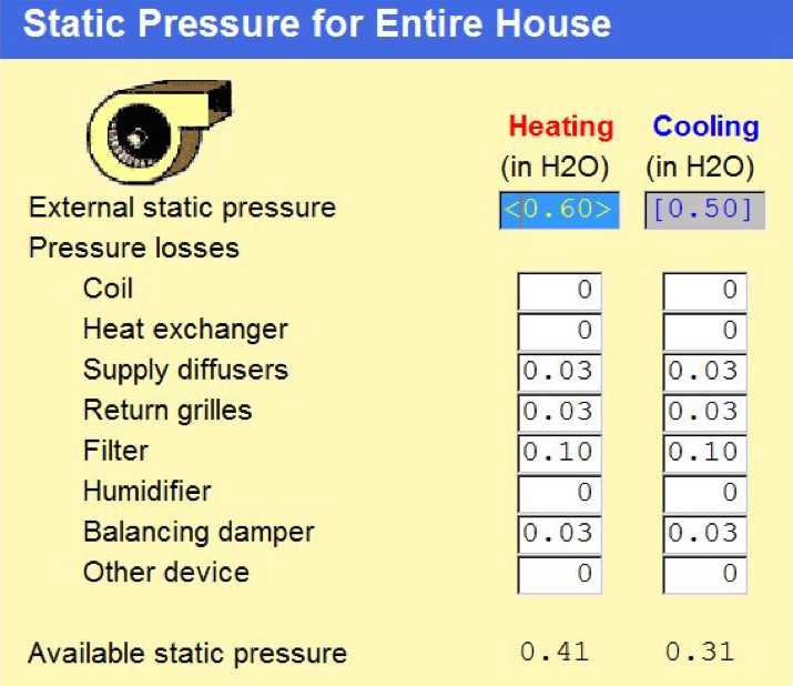
At the top is the total external static pressure. That gets entered automatically after you select equipment, but you can override the numbers here. In the table above, I’ve got different numbers for heating and cooling just to illustrate the effect on the bottom line, but usually those numbers are the same.
Next, you enter all the external pressure drops. The coil and heat exchanger are zero here because the coil is already included in the total external static pressure because it’s inside the AHU and there is no heat exchanger since it’s a heat pump. With a furnace, you’ll have a coil that’s outside the AHU and will need to add it. I don’t think we’ve ever had a project where the heat exchanger was external and needed to be added here.
The other numbers shown there are pretty standard numbers, but you want to enter the actual numbers if you have them. For example, if you’re using wooden grilles, the pressure drops will be significantly higher. But please, please…don’t use wooden grilles! They will make it very difficult to get good air flow.
Your duct budget
Once you’ve entered your external static pressure rating and all your external pressure drops, what’s left after subtracting the drops from the rated pressure is the available static pressure. That’s how much you have left to “spend” on your duct system.
To summarize where we’re at now:
- The blower creates a pressure rise to move air through the ducts.
- It’s rated for a certain amount of air flow at a specific total external static pressure.
- The ducts, fittings, and other components cause pressure drops.
- Subtracting the pressure drops for all the things that aren’t ducts or fittings from the total external static pressure yields the available static pressure.
- The available static pressure is the pressure drop budget you have to work with when designing the ducts.
We now go to the next step and design a duct system that will have a pressure drop of no more than the available static pressure. To do that, we size ducts and choose fittings using something called equivalent length. And that’s the subject of the next article in this series.
Buy the ACCA Manuals on Amazon*


Allison A. Bailes III, PhD is a speaker, writer, building science consultant, and the founder of Energy Vanguard in Decatur, Georgia. He has a doctorate in physics and writes the Energy Vanguard Blog. He also has a book on building science coming out in the fall of 2022. You can follow him on Twitter at @EnergyVanguard.
Other articles in the Duct Design series:
The Basic Principles of Duct Design, Part 1
Duct Design 3 — Total Effective Length
Duct Design 4 — Calculating Friction Rate
Duct Design 5 — Sizing the Ducts
Related Articles
The 2 Primary Causes of Reduced Air Flow in Ducts
Don’t Kill Your Air Flow with This Flex Duct Disease
The Science of Sag – Flex Duct and Air Flow
The Secret to Moving Air Efficiently through Your Duct System
* These are Amazon Associate links. You pay the same price you would pay normally, but Energy Vanguard makes a small commission if you buy after using the link.
This Post Has 20 Comments
Comments are closed.
you wrote: “For example, if
you wrote: “For example, if you’re using wooden grilles, the pressure drops will be significantly higher.”
Not a good example. Given your long-standing focus on the dark side of residential HVAC, any mention of wood grilles within these hallowed walls should only be in the context of admonition!
Yes, you’re absolutely right,
Yes, you’re absolutely right, David. I got caught up in the main subject and neglected my duty there. I’ve just added this to the end of that paragraph: “But please, please…don’t use wooden grilles! They will make it very difficult to get good air flow.”
At some point it may be worth
At some point it may be worth pointing out that like many other budgets, it is worthy not to expend every available asset if avoidable.
In the case of air handlers with smart ECM blowers (SEER 15 and up, typically) the system will either punish or reward for ductwork. If the ductwork (and air filter) are sized or otherwise selected and installed for lowest feasible static, then an ECM blower will reward that happy condition with very quiet and efficient operation.
Conversely, if the ductwork and air filter conspire to gobble up the entire static budget (or more) the ECM blower will punish that typical condition with noisy and inefficient operation, followed, perhaps, by an early demise.
One question for
One question for consideration: What happens when an existing duct system is employed with a downsized air handler installed as part of a highly effective energy retrofit. For example, when a 5 ton system is downgraded to a 3 ton because of a newly encapsulated attic with continuous rigid foam under the siding. Now a nominal 2000 cfm capable duct system might present much lower low static pressure when driven by a 1200 cfm air handler.
Low static in airways is a
Low static in airways is a non-issue, although dropping from 5 tons to 3 tons would likely require re-balancing (assuming system was ever balanced in the first place!) since fittings have non-linear friction losses.
In my experience, the duct system was likely undersized for the original system, so a smaller system will end up being significantly less oversized than the nominal tonnage would suggest, especially if the new system operates at greater than 400 CFM/ton, which is often beneficial. I’ve seen situations where the original duct system was still undersized after downsizing by a ton!
In general, when it comes to duct static, lower is better, especially on the return side. As for supply side static, there’s one caveat to keep in mind when dropping by such a large percentage. When supply velocity is reduced, register throws will get shorter. Whether or not that becomes an issue depends on how well the house is insulated and sealed. In general, the more efficient the envelope, the less important throw patterns become. I would argue that for homes built to 2012 IECC or better, throw patterns are irrelevant. Ditto for supply register placement.
Great reply, David.
Great reply, David.
One thing I might add regarding supply register throws with high performing building envelopes is, in context of cooling mode, that a high performing envelope will not provide as much reheating of chilled supply air as a marginal performing envelope. Therefore it’s cause to revisit the importance of good throw principles, meaning don’t direct air onto occupants, whether the envelope is high performing or not. As building envelope thermal performance is improved, the burden of reheating supply air shifts toward internal heat gains vs. gains through the enclosure. If the internal gains are modest, and register selection and/or placement is poor, comfort complaints will come from the occupants.
Absolutely, Cameron. I should
Absolutely, Cameron. I should have clarified that my comment (re: register placement being irrelevant in high performance homes) specifically referred to the presumption / rule-of-thumb that supplies should be located at the perimeter, where the load is. In most cases, you only need to get the air into the room.
To your point… when laying out a duct system, one must always avoid feedback between supply and return, as well as avoid directing supply air at seating or standing areas.
Along the lines of what Mr.
Along the lines of what Mr. Parker said, I read that many many AC installations are criticized for having excessive ESP (External Static Pressure). And many AC installations are over-sized by any rational measure. It might be nice to think about making the duct system more appropriate, by reducing AC tonnage and therefore airflow. Perhaps a couple of case studies may be presented.
Is it necessary to replace
Is it necessary to replace the lineset when replacing you A/C unit.
Marion wrote: “Is it
Marion wrote: “Is it necessary to replace the lineset when replacing you A/C unit.”
That depends on several factors. Generally speaking, if new system is equal or smaller tonnage and uses same refrigerant, and the original lineset is not damaged, then replacement isn’t usually necessary. However, each brand/model/size has specific limits on equivalent length and minimum diameter that must be followed.
When changing from R22 to R410 refrigerant, the lineset must be purged of incompatible chemicals from the R-22 oil. Established cleaning procedures must be followed, including post purge testing.
Having a little trouble
Having a little trouble understanding your example with the software you used to determine allowable SP for duct design… If you have a system, lets say a HP since that is what you described above, and the AH is a one piece with a coil pre-installed. The AH is rated for a max of .5 in wc TESP. Regardless that the coil is pre-installed, it still has a pressure drop that the blower will be “seeing” under normal operation, just like the filter media, and electric heater elements. Why did you not include the coil pressure drop or the electric heater pressure drop in your example? You say that in your example, we would have .41 in wc static pressure left to “play around with” when designing the duct system! I can’t wrap my head around where you are factoring in the coil drop in your calculations? Any help would be greatly appreciated??
@Mark, external static, by
@Mark, external static, by definition, accounts for permanently affixed internal components such as the heat exchanger in the case of a furnace, or the refrigerant coil in the case of an air handler. So to answer your question, the coil in Allison’s example has already accounted for in the blower table’s external static specs.
OTOH, a heat strip kit, if present, is considered ‘external’ because the size and thus pressure drop is unknown by the manufacturer. The installation manual should have a table showing how much static to subtract for each kit.
Cabinet mounted filters, especially when shipped with the unit, are typically accounted for in external static, although designers should always verify one way or the other. In many cases blower tables include a footnote indicating how much static was subtracted for the filter. That way if a more (or less) restrictive filter is installed, only the difference would be subtracted from available static.
@David — So, if I have an AH
@David — So, if I have an AH which indicates that it has a max allowable static pressure of .5, then the only static pressure measurements I need to be concerned with exceeding .5 are the non-factory filter racks, and whatever heat pack I have installed, and the ductwork itself? Therefore, I would take my measurements with a probe in the blower compartment for the negative side and a probe above the coil, but below the heat pack for my positive pressure, and add them together to get the less than .5 (hopefully) SP that is max for that unit??
Mark wrote: “I would take my
Mark wrote: “I would take my measurements with a probe in the blower compartment for the negative side and a probe above the coil, but below the heat pack for my positive pressure, and add them together…”
Just to clarify, most AHU’s have the coil on the negative side of the blower (Trane Hyperion is one exception that comes to mind).
Regarding probe placement, it’s easier/better to drill the plenums instead of the AHU cabinet. In that case, subtract the heat strip kit static spec from the SP numbers given in the blower table. Either way yields the same result. Also, if the blower table includes a factory filter (typically @ 0.10 IWC) and it’s not being used, you must add that back to the blower table numbers.
In my experience, most air handlers have a higher maximum static than 0.5 IWC. Also, virtually all air handlers have more than one speed tap or setting, sometimes with different maximum ESP per speed. In any case, never use the AHU’s maximum ESP as your target. Keep in mind that the filter resistance will increase over time as it collects dust. More importantly, blowers are less efficient at the top of the fan curve, especially ECM’s. It’s best to stay in the middle of the range. If you have to use max static to get the design airflow, consider using a different air handler!
Once you determine the appropriate design airflow, study the blower table and determine which speed yields the desired airflow at an acceptable ESP, interpolating as necessary. I typically specify ‘not to exceed 0.4 IWC TESP’ for conventional air handlers, but I go lower for ducted mini-splits and other low static AHU’s. The objective is to stay within the blower’s ‘sweet spot’ in terms of efficiency. Unfortunately, residential equipment manufacturers don’t publish fan curves. However, if the blower table includes Watts for each static-speed combination, you can easily calculate blower efficiency (CFM/Watt) for a few points within your target range.
Thank you for the detailed
Thank you for the detailed explanation. I currently have a fixed speed AHU fan supplying air to a number of different zones. However, each of the zones is controlled independently by its VAV box with a room controller (with sensor). When all VAVs are closed or running at their minimum speed, the idea I have is to make use of a pressure relief damper to release the excess air into the ceiling void since it’s a constant volume system. The question I have is how do I know the pressure setting required for the pressure relief damper and what’s the best location for the pressure relief damper to accurately capture the pressure buildup and release?
@Abiola, the pressure setting
@Abiola, the pressure setting (or more typically the position of the counterweight on the relief damper) must be determined empirically by measuring the airflow at the AHU. The latter can be done with a TrueFlow® meter from Energy Conservatory or by taking external static pressure measurements at the AHU and refer to the blower table for the unit. The idea is to maintain a respectable minimum airflow across the heat exchanger. The minimum flow depends on whether the blower is associated with a furnace, heat pump, straight A/C, etc, and in the case of A/C, which climate zone you’re in. That’s another discussion if you need some help with that.
Dumping relief air in the ceiling void avoids the issue with more common bypass ducts (i.e., routing relief air directly back into the return side close to the AHU, which is a bad idea on several levels). However, your plan has other risks: in particular, creating a pressure imbalance between ceiling void and rooms, which will induce more infiltration that if the system were balanced. You can mitigate (but not eliminate) this issue by ensuring the ceiling void communicates with room air, but that in turn could lead to excess cooling (or heating) in the spaces where that air exchange occurs. There’s no free lunch with fixed capacity equipment.
BTW, if your AHU is variable speed, constant volume (i.e., ECM motor with constant volume logic), then it will attempt to maintain the selected airflow volume, but at a cost of higher energy consumption. In that case, you’ll set the relieve damper using a power meter rather than based on air volume, keeping in mind that you still need to make sure external static at the AHU doesn’t exceed the maximum for the unit.
Lastly, you asked about positioning the relief damper… It doesn’t make any difference where it’s located as long as it’s upstream from all VAV boxes.
I was wondering about what
I was wondering about what exactly is totaled and subtracted from ESP to find ASP. For example: If my idea for a duct system includes 13 total supply vents, and I wanted to place dampers prior to each one to be able to dial in each room more precisely, would that mean that of my .5 inwc budget I have already used up 0.39 before even factoring in any of the ducts or fittings? Also, I was wondering about filter returns. Assuming in the same system I have 9 returns, all with filter boxes, and a filter in the return plenum, would that eat up double my total (10 x 0.1 = 1 in wc). And can this be largely ignored my over sizing the returns? Say my system requires 600 CFM total for the house, but I have the return set up to be able to handle 1,200 cfm or more. Would the filters even matter at that point?
IF YOU ARE DESIGNING A SYSTEM
IF YOU ARE DESIGNING A SYSTEM, REGARDLESS OF THE AMOUNT OF RUNS OR CFM, THEN YOU CAN DO IT WITH A STANDARD DUCTULATOR. MATCH 600 CFM WITH .1 FRICTION LOSS FOR SUPPLY RUN OFF UNIT AND 600 CFM AT.05 FOR RETURNS. THAT WILL GIVE YOU ROUND OR SQUARE DUCT SIZE THAT IS OPTIMAL. THEN IF YOU NEED LETS SAY TWO 100 CFM SUPPLY REGISTERS AND YOU BRANCH THOSE OFF ABOUT 2 FEET DOWN THE LINE, THEN FIRST YOU WOULD CHECK 100 CFM AT .1 (BC IT IS SUPPLY) AND FIND YOU WOULD RUN A 6 IN ROUND PROB. THEN AFTER THE TWO TAKE-OFFS AT 100 CFM A PIECE, YOU NOW HAVE 400 CFM TO DEAL WITH… NOW YOU CAN RUN DUCT SIZED FOR 400 CFM AT .1 FR INSTEAD OF 600. AND SO ON AND SO FORTH.
@Adam, the static rise and
@Adam, the static rise and drop (resistance) of multiple supply or return branches are not additive! Allison covers this in the next article in this series (see link at end of article) where he writes: “choose the (duct run) that has the greatest total effective length. You do NOT use the sum of all the ducts and fittings.”
With 9 returns with filter grilles, you are correct that filters won’t use up much of the available static. Aside from considering the resistance of the ‘greatest total effective length’ path, you should calculate average filter face velocity (CFM / filter face area in ft2). Ideally, you’ll want face velocity to be less than 200 feet per minute, which works out to 6 ft2 if system airflow is 1,200 CFM. Check out Allison’s article “The Path to Low Pressure Drop Across a High-MERV Filter” on that topic.
Thanks for the info , it’s
Thanks for the info , it’s been years since I’ve had to look at a manual D. When you’re figuring the pressure drops for AESP , do you add the drop for every register ? I wasn’t sure if you did all or just on the TEL .
Also in the comment above from someone else, can you design any duct system off of a .1 supply and .05 return?
I see some guys do a .1 for both , but if either are true, why do all the other work like TEL, AESP etc
Thanks