The Basic Principles of Duct Design, Part 1
When it comes to heating and cooling homes, forced air distribution is king. Yeah, my Canadian friend Robert Bean of Healthy Heating pushes radiant for both heating and cooling, and my Texas friend Kristof Irwin drank that koolaid and installed what may be the first radiant cooling system in Texas. Even if radiant distribution systems completely take over, though, we’ll still need forced air duct systems. Why? Because we still need to move air for ventilation and, in humid climates like the southeastern US, dehumidification.
So, if we’re going to move air through ducts, we need to understand the physics of air and how we make it do our bidding. In this series of articles, I’ll take you through these things. Today I’ll start with what you do in the HVAC design process before you get to the duct design phase (Manual D) as well as the physics of air flow when it’s constrained by ducts. I’ll follow that up with articles on the process we use in designing duct systems, including available static pressure, equivalent length, and choosing fittings.
Ready?
Before duct design
Designing a duct system is important but there are a few critical steps that come first. Number one is the heating and cooling load calculation using a protocol like ACCA’s Manual J* or the ASHRAE Handbook of Fundamentals.* You’ve got to know how much heating and cooling you need for each room (in BTU/hr). Then those BTU per hour requirements immediately translate to room-by-room air flow requirements in cubic feet per minute (cfm). It’s done automatically in the software we use (RightSuite Universal by WrightSoft).
Once you know the BTU/hr and cfm numbers for the building, you need to select the right equipment for heating and cooling. ACCA’s Manual S protocol* helps you do that. There’s more to it than just finding a piece of equipment that meets the total heating and cooling loads for the home. You’ve got to make sure you adjust for the indoor and outdoor design conditions of the home. Ideally, you have the manufacturer’s performance data tables to help you get it right.
Then you’re ready to start designing the duct system.
The weight of air
The first thing you need to know is that air has weight. David Hill has given a couple of great presentations on duct design at Building Science Summer Camp and this is his starting point. (See Michael Chandler’s excellent summary of Hill’s 2011 Summer Camp talk on Green Building Advisor.) In the photo below, Hill holds a 1 cubic foot block, which he says would weigh nearly 0.1 pound if it were air. The actual number is 0.0807 lb at standard temperature and pressure.
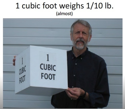
If you have a 2.5 ton air conditioner, the nominal air flow would be 1,000 cfm. (The rule here is 400 cfm per ton.) That means the blower has to push about 81 pounds of air through the system each minute. It takes work to move weight around.
Well, actually, if you remember your introductory physics class, you know that’s not quite true. You can move weight for free if you move it horizontally and without any kind of resistance. It takes work to move it upward against gravity or to push it any direction against friction. And that brings us to…
The physics of air flow
If you take a fan out into your yard on a calm day and turn it on, you’ll get its maximum air flow. If you take that same fan and blow the air into a cardboard tube, it has to work against the pressure that builds up in that space. The more you reduce the size of that tube or make it longer or turn the air with it, the more static pressure builds up. And the more the air flow is reduced.
That’s the basic principle you have to work with in duct design. I’ve written previously about the two factors involved in reducing air flow in ducts. One is friction. As the air moves through a duct, it interacts with the surfaces. The smoother that inner surface is, the better it is for air flow. The rougher the surface, the more it slows down the air.
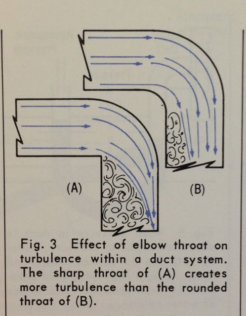
The second factor is turbulence. This generally arises when you move air through fittings, or when you turn the air. With rigid duct, you turn the air with fittings, but unfortunately that’s not always the case with flex duct.
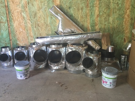
When air comes out of the air handler, several things happen to it. It gets sent to the various rooms in the house. As it travels through a trunk-and-branch duct system, the quantity keeps diminishing because some of it gets diverted down each branch on the way to the end.
Each section of duct, each fitting, each turn of the air adds resistance to that air flow because of friction and turbulence. Grilles and registers, filters, and balancing dampers also add resistance. That resistance results in decreases in the static pressure, or pressure drops.
So, we begin at the blower with a high pressure. By the time the air comes out of the supply vents, that pressure has dropped to zero (relative to room pressure).
The next step in the duct design process
In the next article, I’ll talk more about those pressure drops and how they determine the available static pressure, which then leads to the total effective length of our duct system. You can get to the other articles in the series with the links below.
Buy the ACCA Manuals on Amazon*


Other articles in the Duct Design series:
Duct Design 2 — Available Static Pressure
Duct Design 3 — Total Effective Length
Duct Design 4 — Calculating Friction Rate
Duct Design 5 — Sizing the Ducts
Related Articles
The 2 Primary Causes of Reduced Air Flow in Ducts
Don’t Kill Your Air Flow with This Flex Duct Disease
The Science of Sag – Flex Duct and Air Flow
The Secret to Moving Air Efficiently through Your Duct System – my article on David Hill’s 2015 Summer Camp presentation on oval ducts
Image credits: Top photo by Energy Vanguard; weight of air photo by David Hill; turbulence drawing from ACCA‘s Understanding the Friction Chart (which apparently is no longer available).
* These are Amazon Associate links. You pay the same price you would pay normally, but Energy Vanguard makes a small commission if you buy after using the link.
This Post Has 10 Comments
Comments are closed.

The presentation style in
The presentation style in this article is very easy to follow. It simplifies complex information for the layperson (or, in my case, the architect). I’m looking forward to seeing the next installment.
Not that it matters for your
Not that it matters for your discussions, but I thought the density of air at STP was 0.075#/ft3
D’oh! Yes, Lee, you’re right.
D’oh! Yes, Lee, you’re right. Actually, we’re both right, but you’re more right. The number I gave in the article (which I’ll change in a moment) was 0.0807 pound per cubic foot. That is correct for dry air, but real air does have water vapor in it. Since water vapor is lighter than dry air, it brings down the average density. At 75° F and 50% relative humidity, it’s about 0.75 pound per cubic foot, as you say.
I am having ac work and new
I am having ac work and new flex duct system run off a main hard board plenum that comes up into the attic out of the ac unit closet. Florida install. The installer wants to run a flex duct directly off the end of the main plenum that comes off the blower/inside unit. I did install for a year in high school and we were taught to have the last run of the main hard board plenum no closer than 12 inches from the end. (to create back pressure) I told the ac guy he can use a prefab sheet metal elbow (12 inch) on a side of the main plenum instead of running it off the top/end. I thought that you never ever want to install anything on the end of the main plenum, even a flex duct system, because it will not allow or will decrease back pressure and therefore decrease airflow in the system?
Referring to the last image
Referring to the last image above:
Would the duct equivalent of these truck aero add-ons be beneficial in reducing the equivalent length of a duct turn with a sharp throat?
http://smarttruckaero.com/products-overview/top-kit/
Duct safe materials, of course.
I’m looking for ways to retroactively reduce pressure drops.
I am noticing a few
I am noticing a few similarities between how water moves in a plumbing system, how current moves in an electrical system, mechanically pulling electrical cable through ducts (think a duct and manhole system, not hvac ductwork) and how air flow moves through an HVAC system.
While installing cable in a duct and manhole system, one has to worry about the friction built up around corners as well as the increased pulling tension it takes pull the cable through the pipe due to the corners (gotta make sure that one does not stretch the limits of tensile strength on the conductor or insulation). Obviously, with HVAC, we are not worried so much about tensile strength of air, but the amount of friction around the corners, I think could be a concern. I understand the lingo in the HVAC industry is “Equivalent length” and that the author addresses it in another article. However, one way to help combat this is with larger radius sweeps as opposed to 90 degree elbows. It allows a smoother transition to the air moving in a different direction. Similar to a car on a road….the bigger the curve, the faster you can take it. A 90 degree intersection will require the car to slow down or flip to make the turn.
Another issue in the electrical sector is the idea of skin effect. Where most of the current flowing through a conductor flows at the edges of the conductor, rather than the the center. Water pipes show the same phenomenon. Turn on your hose and notice that the water sprays from the sides and not the center. What we find in the electrical world, is that a 4/0 stranded conductor can carry a bit more current than a 4/0 solid conductor. So, I wonder if multiple, smaller pipes would lessen the pressure requirements at the blower motor? The idea is less turbulence in the center of the pipe and more consistent air flow across the entire pipe diameter.
Also, in the electrical world, if we have 2 separate, but equally sized conductors, starting and ending in the same spot, but tied together at both ends, the resistance drops by half. I have noticed similar behavior with water. And I wonder, since ducts all have the same starting pressure and ending pressure, if you were to run parallel groupings of smaller pipe (multiple outlets in the same room), if the amount of resistance from blower motor to room would drop? That would also lower the amount of pressure the blower would have to surpass to move the air.
I also wonder if other
I also wonder if other materials can be used for ductwork. In caustic environments, cpvc pipe is used. In the power industry, High Density Poly Ethelene (hdpe) pipe is used. They do make a low smoke version for use in confined spaces like electrical vaults and substation basements.
The reason why I am looking for something besides sheet metal pipe is 1) plastic is a much better insulator and therefore less heat is loss through convection of the duct itself. Sure, you can insulate a sheet metal duct, but why not buy a pipe where that is not necessary?
Another reason is the smoothness of a plastic pipe is better than even galvanized steel, which would then be better to reduce the turbulence mentioned in the article. And because it is a better insulator, there is less sound produced within the pipe than there is in typical sheet metal duct.
A third reason is that plastic pipe can be made stronger than sheet metal. Much lower rates of dents that occur in transit or installation.
A fourth reason is that proper installation requires the pipe to be either fused together or joined by some sort of adhesive. This makes it air and water tight. No additional sealing required (think duct tape that is used with sheet metal duct), which would make for easier and quicker installation.
I understand the two prevailing thoughts against using plastic pipes are the flammability and smoke specs. However, plastic pipes have been made to follow these standards. And by code, I can use different material that burns (like wood) as long as I have 1/2 inch of gypsum board covering it. So, I don’t see these as insurmountable obstacles.
Plastic pipe is also used in water systems, even hot water boiling systems…where the water temp is hotter than any residential plenum should ever get.
Hey Allison,
Hey Allison,
thanks for posting this informative article but I am confused by these statements you made:
“The more you reduce the size of that tube or make it longer or turn the air with it, the more static pressure builds up. And the more the air flow is reduced.”
and
“Grilles and registers, filters, and balancing dampers also add resistance. That resistance results in decreases in the static pressure, or pressure drops.”
does resistance increase or decrease static pressure?
Remodeled home,Attic mounted
Remodeled home,Attic mounted HVAC unit, Return box mounted approx 18″ from side of AHU end, has 20″ flex duct attached and run in a big loop (10-15ft) around to the end of the AHU. Wouldn’t it be better to just have the duct run directly (18″+/-) to the AHU?
Fred, yes, it would
Fred, yes, it would absolutely be better for air flow to shorten that duct. A lot of poor air flow problems in ducts are on the return side so anything you can do there to fix it should result in noticeable improvement. Two possible reasons your return duct is so much longer than it should be: (1) The installer did it to reduce the transmission of noise from the blower into the living space; or (2) the installer was too lazy to cut the duct.