Duct Design 5 — Sizing the Ducts
To this point in our little series on duct design, we’ve been calculating intermediate quantitites: available static pressure, total effective length, and friction rate. Today we use all that to find out how big the ducts need to be. We’re following the Manual D protocol for duct design, a standard developed by the Air Conditioning Contractors of America (ACCA). Let’s jump right in and see how it works.
Sizing the ducts by friction rate
Recall that the rated total external static pressure (TESP) tells us how much resistance we can have across the furnace or air handler when it’s delivering the rated air flow. To hit that number, we have to control the resistance of the duct system.
All else being equal, a duct system with a greater total effective length (TEL) has greater resistance. That doesn’t mean the total external static pressure is greater, though, because the friction losses in the ducts depend on both the length and the cross-sectional area. That’s the unequal part, the knob we use to control the resistance.
If the total effective length is high, we have to increase the duct area. If the length is low, we can use smaller ducts. That’s how we ensure the ducts deliver the right amount of air. (Of course, it has to be installed and commissioned, too.)
The friction rate I discussed in part 4 of this series allows us to quantify this process. (It’s one of two factors that we have to look at in determining the size. The other is below.) In part 4, I showed an example where the friction rate was 0.073 iwc per 100′ of total effective length.
The next step is to use that friction rate and the air flow rate for each duct section in cubic feet per minute (cfm) to find the size necessary to move that amount of air. We do it with software, but duct calculators give the same information.
Here’s an example with the new ASHRAE duct size calculator. Our friction rate is 0.073 iwc/100′. Let’s say we have a section of ductwork that needs to move 400 cfm. On the Friction Loss/Air Quantity part of the dial, we line up 0.073 with 400 cfm, as seen below.
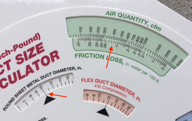
As you can see, we need a round metal duct that’s slightly larger than 10″ to do what we want here. For flex installed properly (inner liner pulled tight with no sag or compression), it would be the same size. (See my article on flex duct compression if you don’t believe that.)
We don’t design for compression, but you can see that if the installer used flex and didn’t pull the inner liiner tight, leaving 4% longitudinal compression, you’d need a 12″ flex duct rather than 10″. If they installed 10″ flex duct compressed by 4%, the resistance would be higher, the static pressure would be higher, and the air flow would be lower.
Got that? The process isn’t hard. You’d do the same thing for every section of the ductwork, using the same friction rate but putting in the different air flow requirements for each part.
Sizing the ducts by velocity
But just looking at those two sections of the duct calculator aren’t the end of the process. We also want to make sure the velocity of the air isn’t too high. So we look at the Velocity/Air Quantity section. In my example here, 400 cfm at 0.073 iwc/100′ corresponds to a velocity of about 725 feet per minute (fpm). That’s fine for supply ducts. To move 400 cfm on the return side in this duct system, we’d need to move to a larger duct.
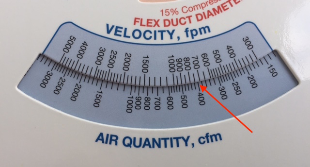
In Manual D, Table N3-1 specifies the maximum velocities for supply and return trunks and branches. For supplies, it’s 900 fpm. For returns, it’s 700 fpm. That’s why we’d go up to 12″ in this case for a return moving 400 cfm at 0.073 iwc/100′.
When sizing by the friction rate results in too high a velocity, we size by the velocity, which results in a larger duct. But larger ducts also result in less resistance, which means we may get too much air flow in that run. What do we do about that? Install balancing dampers.
In our HVAC design business at Energy Vanguard, we generally don’t specify ducts smaller than 4″. We do round ducts in one inch increments from 4″ to 10″ and then every 2″ after that, which is why I said we’d use a 12″ instead of a 10″ duct for a return in that example.
Now we’ve got the procedure for finding the sizes of all the ducts in a design. I’ve got only a few topics left to go in this series: laying out the ducts, choosing duct types, and registers and grilles. And then I’ll present a case study to show how all this works, from design to installation to commissioning.
Buy the ACCA Manuals on Amazon*


Other articles in the Duct Design series:
The Basic Principles of Duct Design, Part 1
Duct Design 2 — Available Static Pressure
Duct Design 3 — Total Effective Length
Duct Design 4 — Calculating Friction Rate
Related Articles
The 2 Primary Causes of Reduced Air Flow in Ducts
How to Install Flex Duct Properly
The Science of Sag – Flex Duct and Air Flow
The Secret to Moving Air Efficiently through Your Duct System
* These are Amazon Associate links. You pay the same price you would pay normally, but Energy Vanguard makes a small commission if you buy after using the link.
This Post Has 42 Comments
Comments are closed.
You should compile these Duct
You should compile these Duct Sizing posts into a PDF format for download. They would be a great help for HVAC Schools.
Gary, we’ll be doing
Gary, we’ll be doing something like that. Our plan is to create online courses with expanded versions of this with homework and videos and more.
Coming soon?? I hope!
Coming soon?? I hope!
John, I’ve just gotten back
John, I’ve just gotten back into working on our online curricula. Look for something on this topic next year, if all goes well.
Hey Allison, thanks for the
Hey Allison, thanks for the great articles! Did you ever finish the series or did it end with 5? Thanks!
Drew,
Drew,
I think 5 is the last article. this article was made in 2017, it probably ends at 5.
Allison, as you know, Manual
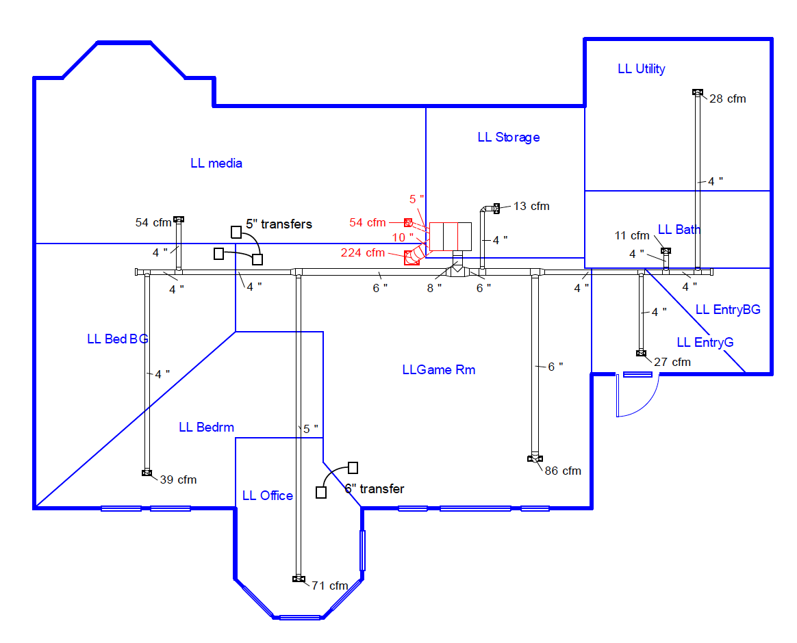
Allison, as you know, Manual D is not the only way to design ducts and it leaves out important considerations such as duct surface area, as evidenced by the long duct runs in your illustration.
It also depends on dampers to overcome the embedded simplifications in the method. As a result there can be higher static pressures, higher fan motor watt draw, and larger conduction losses.
ACCA Manual D covers one set of procedures that can be followed for proper design of a duct system. It contains the information necessary to:
• determine the maximum allowable duct static pressure to ensure the design airflow can be delivered through the unit and to each room;
• take into account the resistance of evaporator coils,humidifiers, air filters,auxiliary heaters, dampers, etc.
• take into account the performance of the air handler fan under differing static pressures.
Other design methods, such as the Equal Pressure Drop method as applied by Davis Energy Group, are available. Some of these methods do not depend on dampers in every run and can provide a more efficient design.
In the majority of homes currently built, duct systems are designed using rules of thumb and obsolete assumptions about house thermal characteristics(Hawthorne and Reilly 2000). A common rule of thumb is that the registers need to be placed towards the perimeter of the house, either below or above windows. These ideas were based on studies from the 1940s and 1950s that concluded that three factors favored these locations for registers: 1) floor warming due to conduction, 2)counteracting window convection currents, and 3) mixing
capabilities. Buildings designed today differ greatly in thermal characteristics and can thus be designed with registers high on the inside wall.
This system optimization strategy has been proven to work in homes built under the Building America program. Thermal distribution efficiency is greatly improved while retaining comfort conditions in the conditioned rooms.
Shorter ducts provide less conduction area and less restriction to flow which provide opportunities for additional improvements elsewhere.
John, yes, there are indeed
John, yes, there are indeed other methods. And yes, the majority of HVAC systems don’t get proper design, instead relying on rules of thumb. Regarding the long duct runs you see in the schematic at the top of this article, we do that for a good reason. Yes, extra duct surface area hurts when the ducts are in unconditioned space. No, we don’t have to put the supply outlets at the perimeter.
We do third party design and don’t always get to work with the HVAC contractor. If we design the system for ducts at the perimeter and the contractor instead keeps them closer in, the design still works. If we design for interior supply vents and the contractor puts them on the perimeter, it may not work so well. Whenever we can, we like to keep the duct runs short.
Thanks, as always, for sharing your wisdom and experience here, John!
If the third party design is
If the third party design is based on supply around the perimeter, but will still work if the supplies are installed at the interior, would it work better, or could the equipment change if the supplies are at the interior and the duct runs shorter?
I’m thinking particularly of ducted minisplits, which I understand need short runs/low static pressure to work effectively and efficiently; does defaulting to perimeter supplies and thus longer runs rule those out in this approach?
Cal, There are many variables
Cal, There are many variables in your question… sure longer duct runs in attics will have more heat loss than short runs. This would be a discussion to have when calculating loads.
There is also the question of register placement on the wall or ceiling. If it is just moving the register 8 or 10 feet from the center to the perimiter, while it may have an effect on the load, it is not likely to have an impact on the static pressure/duct sizing. The average 90 degree elbow has 3 times the impact on the friction rate at 20-35 EL (equivalent length) as an 8 foot straight line length extension. However, moving from wall to ceiling would likely add or remove a fitting, probably have different boot AND quite possibly a different register size. These changes can have significant impact.
Keeping in mind the lower available static pressure available with many ducted mini-splits, making sure there is coordination and agreement on layout and placement is important at the design stage. Having to run an extra 8 or 10 feet of duct is not likely to impact the performance, where adding one or more elbows would be cause to verify acceptable performance.
Nothin’ to add to what Andy
Nothin’ to add to what Andy said.
If you’re considering a ducted mini, be aware that some brands/models have much lower available static than others. As I recall, Daikin’s smallest sizes only have 0.12 IWC available static, which is barely enough for filteration. Mitsubishi’s SEZ head can handle 0.20 IWC, and Fujitsu’s ARU head goes up to 0.35 IWC. That’s a huge difference in terms of how much ducting can be supported by each of these units.
Adding to John’s comment,
Adding to John’s comment, Manual D is like a cookbook… it’s a step-wise approach to duct design with inherent simplifications (i.e., compromises), and the software the implements Manual D imposes even more compromises. For example, in a well designed system, fittings represent most of the pressure drop. However, the most popular duct design software doesn’t adjust fitting equivalent lengths for actual velocity as specified in Manual D (see my comment in part 3).
That said, this series is an excellent primer for ‘pros’ who haven’t bothered to read Manual D and rely totally on the software.
BTW, I follow my own version of the equal pressure drop method John mentioned and I totally embrace short duct run-outs. Extending supply run-outs to the perimeter is silly/wasteful in homes built to 21st century energy codes.
Thanks, David. I agree short
Thanks, David. I agree short run-outs are the way to go but, as I said in my reply to John Proctor, sometimes you have to compromise when you’re doing third party design. If I were a builder or HVAC contractor, all my systems would have short run-outs — or no run-outs, as in ductless mini-splits. Most of our designs are for ducts inside the building enclosure, so that mitigates the extra heat gain and heat loss associated with higher duct surface areas.
Yup, doing HVAC design
Yup, doing HVAC design without the ability to coordinate with the installer limits our flexibility to do everything as we would want it.
Probably the biggest push-back I get from contractors is my requirement for ductless return whenever possible, using various methods to ensure a very low static return path from every supply. That not only reduces static but saves first cost and blower energy (return side is typically the worst offender in systems with excess static). It also makes it a lot easier to get ducts inside floor trusses. But for some reason, most mechanical contractors can’t get their head around systems with ductless or single point return.
In low-load homes with finished basements, I require ductless return. The sensible load in the basement is typically far too small for it’s own system, even with mini-split. A ductless or single point return in basement forces air changes between floors even when there’s little or no sensible load in the basement. This helps avoid supplemental dehumidification and keeps the basement fresh, and acts to reduce the overall load. To me, it’s a real no-brainer.
David,
David,
I am trying to wrap my head around the “ductless return” idea:
Obviously you are using sealed combustion equipment, so back drafting is not a concern.
This is in new homes, so Radon resistant construction is in play, and you would not be pulling soil gas from the ground.
Are you under cutting doors, and making passive return holes to the basement?
How does this work for AC return; i.e. how does the hot, moist air get back to the finished basement?
@Rhett, thanks for asking. I
@Rhett, thanks for asking. I posted details elsewhere in this blog, but it’s useful to review for those who are interested.
Most of my projects have heat pumps and no fossil fuel appliances. I advise clients to avoid combustion appliances in low load home. But in cases where there’s a gas water heater or boiler, yes, they must be sealed combustion. But they should still be isolated from an open return — either by adding a partition wall (closet) around the ng appliance, or by ducting or sleeving the return to an oversized grille in the mechanical room wall.
Regarding radon: ductless basement returns only apply to finished basements. The open return doesn’t change the pressure balance with respect to the outside, so the air handler doesn’t “pull in” soil gas as you suggested. This setup is much safer than the status quo unsealed crawl space construction found in much of the country. In areas where there’s potential for in-ground radon, an active sub-slab ventilation system is warranted.
Return paths are evaluated based on design supply CFM per room. Options include jump ducts, direct, offset or baffled transfer grilles and door undercuts(typically no more than 1″), depending on the situation. For nominal undercuts are typically sufficient for bathrooms and laundries (up to 2 CFM per sq.in. of gap). In low load homes, as are most of my projects, undercuts are adequate for small bedrooms, where design airflow is often < 50 CFM. The return path from main floor to basement is typically via the stairway, either by not having a door, or using a louvered door. Otherwise, if the mechanical room is adjacent to or beneath the stairs, a transfer grill can be installed in the sidewall of the stairwell if there's a door at the bottom of the stairs. In general, I advise clients that it's a bad idea to shut off a finished basement from the rest of the house. If house and mechanicals are properly designed, there should never be any 'hot moist' return air in the house.
Here is some food for thought
Here is some food for thought. You could install a return grill and a foot or two of lined duct with a backdraft damper. This would keep sound and heat/cooling to a minimum when the unit is not running. You would not need to under cut doors and run anymore return. They would act as transfer grills and save a lot of money.
A “less than” symbol in my
A “less than” symbol in my last comment caused the parser to truncate the sentence. It should read:
“In low load homes, as are most of my projects, undercuts are adequate for small bedrooms, where design airflow is often less than 50 CFM”
Another thought about Manual
Another thought about Manual D…
I’ve had more than one builder ask me to prepare a Manual D for LEED certification – after the fact! Sigh.
Here’s my take on Manual D submittals: Programs and codes that require a Manual D report for compliance are missing the boat. It’s just a piece of paper, rarely if ever, followed by field verification that the ducts were actually built to plan, or that the design itself was any good. Far better would be require external static pressure and room-by-room airflow verification. Prove to me that you *build* good duct systems, not what some computer program spits out. I could care less how you got there.
David, we’re in complete
David, we’re in complete agreement here. We also get — and turn down — the occasional request for load calculations and duct designs after the system has already been installed.
I spent years doing field
I spent years doing field investigations of poorly performing or prematurely failed residential HVAC equipment. So often, so often, the cause was related to ridiculously poor airflow often caused by exceptionally poor duct installations and lack of maintenance, or even worse, both! I asked building officials why an occupancy permit was granted without a proper test & balance being done beforehand and they would simply say it’s not required. In my opinion, residential TAB work should be done before the interior partitions are boarded so that any necessary repairs can be made to defective systems with minimal damage. A laminated drawing of the approved duct design should stay with the building for reference whenever system problems arise or system renovations are needed.
Return air from the upper floors should be ducted instead of pulled through nominal wood stud spaces with a 3″ x 13″ hole cut into the bottom plate. Many times the partition doesn’t fully line up with the joist space meant to conduct the air to a jumper duct some hundred or so equivalent feet away. Just terrible, it’s a tribute to the equipment that it lasts as long as it does under these conditions.
Allison: ” I’ve got only a
Allison: ” I’ve got only a few topics left to go in this series: laying out the ducts, choosing duct types, and registers and grilles.”
Are you going to publish these remaining topics? What you’ve done so far is excellent and very informative! I’d really like to see the last topics. Thanks.
-John
John, thanks for prodding me
John, thanks for prodding me to finish this series. It’s been in the back of my mind since May, but I’ve just let it sit there. I’ll get the next one out next week.
Great! Looking forward to it.
Great! Looking forward to it. Please send out a notice when you post it so we know. – john
I agree with John, registers
I agree with John, registers also need to be put in the calculations (Code). I have tested many homes with HVAC comfort issues with great duct systems but with wooden register choking off 50% – 85% of the delivered air flow. For example, I’ve inspected a “Greatroom” designed air flow of 6 runs with 100cfm’s each (total 600cfm) and actual measured air flow of 18-22cfm’s each (total 120cfm’s). There was no communication between homeowner and GC, nor any from GC to hvac contractor changing flooring type, carpet to hardwood floors therefor change from metal registers to recessed wooden registers and whammo comfort issues.
Doug/Allison et. all – A few
Doug/Allison et. all – A few suppliers of wooden registers provide the free air of their product (many do not). Acknowledging wooden registers usually require a larger boot to equal the same free air as the metal registers, as long as their free air is equal to or just slightly more than the original design with the metal registers, will they work?
The metal register mfgs provide data for spread, throw and face velocity/pressure loss at different CFM, but mfgs of flush/recessed wood registers do not show this data, and if you call and ask, they advise they don’t have it as they have not done any testing. Does anyone know of any?
@cal, I steer clients away
@cal, I steer clients away from wood grilles. None of the manufacturers I’m aware of provide engineering data for wood grilles (although it’s been a few years since I last checked). Hart & Cooley has arguably the most comprehensive engineering data for its extensive lineup of HVAC grilles – but not for their wood grilles.
I’d be curious to see the specs provided by the suppliers you refer to. In addition to the net free area (typically specified as the “Ak factor”), designers need to know the throw distances at various airflows. Net free area doesn’t tell you that.
To answer your question, even with data to estimate size required to get the same free area, I still wouldn’t recommend. The thick ‘vanes’ create turbulence, which greatly reduces throw distance and disrupts the diffusion pattern such as it is. Also, there’s no way to adjust the throw angle. (For the same reason, I don’t typically recommend stamped metal supply grilles.)
If you don’t recommend wooden
If you don’t recommend wooden grilles nor the stamped metal ones, what other options are there and can you include an example. I am a homeowner trying to self educate to ensure my planned build for this fall is more technically correct than the one I am currently living in.
@Alex, for the floor, I like
@Alex, for the floor, I like the Hart & Cooley 531 and for sidewalls and ceilings, I like the H&C A61x and A71x series, depending on the application. I also like Titus 300RS/RL ceiling registers.
Stamped grilles are fine for return air. I sometimes specify stamped grilles for supplies that don’t require an adjustable throw pattern.
Understood they are not
Understood they are not “recommended.” Sometimes the aesthetic design requires wood supply registers in a wood floor (architect, client, etc.). In the case where you are going to have them, what is the best type, brand, strategy, etc. to minimize issues?
@Cal, as I’ve never specified
@Cal, as I’ve never specified or evaluated wood grilles, I’m unable to recommend a particular brand. I just checked Hart & Cooley website and current catalog and they apparently discontinued its Classics line, which included some wood floor grilles (although without any engineering data). Can’t say I’m surprised.
If I were forced to design a distribution system with wood grilles, I would obtain samples of the grilles so I could measure the net free area (simple to do) and then increase the grille area and/or number of supplies per room accordingly to ensure those thick vanes don’t create more resistance than a baseline grille. And I would make sure the installer tests the blower to ensure it produces the design airflow without exceeding my static pressure budget.
Note that the throws produced by a wood grille are typically straight (non adjustable), but throw distance and direction have become relatively less important in homes built to today’s energy codes. The main objective in duct design is to get the right amount of air to the room without expending more energy than necessary to deliver it.
Great series and great
Great series and great comments in the discussion! Just wanted to give you another nudge towards continuing it ;). Thanks
Dr. Bailes,
Dr. Bailes,
Thank you for some great articles on Duct Design. You have clarified the Duct Confusion Calculator. I was shown how a duct calculator worked by an older person who had been installing duct work for years. He put friction loss at .1 and said a six inch duct would deliver 100 cfm . I have read manual D cover to cover over the years,five or six times and have done TEL calculations by hand. The duct calculator never made sense in the Friction Loss area, because as you went up in friction loss the cfm’s went up for the same size duct. I was once blind , but now I see. It has been labeled wrong all these years. Thank you and keep preaching brother
If the series of articles
If the series of articles attempted to explain parts of the software calculated values, then it would have been informative. The series started out well, but ultimately failed miserably.
Ah, yes, because
Ah, yes, because understanding parts of the software output is all that’s important. I keep getting confused about that and thinking that understanding what’s going on behind the software’s interface and outputs is what’s important. Thanks for straightening me out on that, Andrew! I look forward to more great tips from you on how not to fail miserably in the future.
I guess my comments were in
I guess my comments were in haste and abrupt. I’m sorry for that. But I’ll explain in a minute. But Im glad you let the real you out here in the open. Your attitude speaks volumes. Your comments do not. The point is you wrote an article. I get from reading the series that you are trying to sell a service.
I am just a casual reader trying to learn about ac design who saw your site. You – the writer of the article – placed a diagram from your software at the top of the article. The article failed for me because you did not incorporate the discussion around the diagram you provided, instead you discussed some simple calculations and how to use an approximation device.
Had you used the article in a fashion that 1. Discussed and showed the calculations based upon a design such as the one you provided, and 2. Added in the use of the dampers you spoke about, and then discussed how the final results changed your basic assumptions, and explained if the design parameters were still applicable afterward, then I would have found the article useful.
To put it another way from reading your series didn’t you write about having an available amount of static pressure kind of used a budget analogy- but then you put in dampers because the flow is wrong, but the friction was right, so then you just stick in dampers. What happened to the budget?
So I understand you may not like a review from a reader who states that the article failed miserably for them. It’s like that sometimes. Maybe I just expected more after reading the first parts of the series.
Andrew,
Andrew,
Thank you for coming back to explain your comment. So what you’re asking is for me to apply the stuff I explained to an example duct system to show how it all works. I agree that would help make it real. I think I actually had a thought about doing that back when I wrote this series. But other work got in the way and I moved on to other topics and never managed to do that. I’ll add it to my list and come back around to it sometime this year (I hope).
I apologize for my snarky response to your terse first comment. And I have no problem with a reader telling me I failed, miserably or otherwise, as long as they tell me why. I don’t always get it right. And I’m far from complete in these articles because I try to keep things short and tight enough for someone to read without too much difficulty. But thanks again for coming back and explaining yourself. Your second comment has been much more helpful.
~ ab3
My apologies again. The real
My apologies again. The real spin is I actually found the first parts to be very informative and well written. The last part was well written, I didn’t fully get to see it all figured out in the end so I guess I felt let down, but didn’t mean it in a personal way. I shouldn’t have put it the way I did and I regret the wording.
This was an incredible series
This was an incredible series. Thanks for taking the time to prepare this.
It would be helpful if “Duct Design 5 — Sizing the Ducts” contained the duct size formulas for round steel, rectangular, and Flex ducts, similar to how you included the Friction Rate formula in Duct Design 4.
Thank you, Allison!
Thank you, Allison!
Great articles which helped me to understand the duct design process.
I’ve read here a lot of comments suggesting various (possibly better different) duct design methodologies. But what I experienced as a new residential hvac service technician.
A) unfortunately, majority of residential hvac contractors have no idea of the heat gain/loss calculations and duct design. They don’t do it and don’t care. And I’ve seen a lot of times how hvac contractors changed duct designs made by engineers. That is really shocking.
B) as a result of point A, I see a lot of customers who complain about cold/hot rooms or floors and who has oversized/undersized equipment.
I think this is a must read for all hvac technicians.
If you have two return ducts
If you have two return ducts/registers for any given zone, is the longest TEL comprised of the entire length of both returns or just the longest return? I am intuitively thinking only the return nearest the longest supply branch would be counted for the TEL, and not both?
Alexander, with two returns
Alexander, with two returns in a duct system, the total effective length counts only the one with the most restrictive path. It may not be the one with the actual longest length as measured with a tape measure. It’s the one with the greatest sum of actual straight duct length plus equivalent fitting length. The bottom line is that only one of the return pathways will count in the TEL.