Duct Design 4 — Calculating Friction Rate
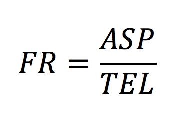
Today’s installment in the duct design series is a simple one. It’s just a straightforward calculation that gives us the design friction rate from the two quantities I discussed in my last two articles. In part 2, I told you about available static pressure (ASP). In part 3, I covered total effective (or equivalent) length (TEL). Today we take those numbers and calculate the friction rate (FR).
Calculating friction rate
Let’s just jump right into it. Here’s how you calculate friction rate:

In part two, I showed a static pressure table from our software that gives us the available static pressure. In that case, the ASP was 0.31 inches of water column (iwc). In part three, I showed a table for total effective length, and our number was 424 feet. Plugging in those numbers, the friction rate would be:
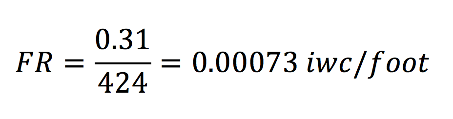
That number tells how much pressure drop to expect in each foot of that duct run. Notice it’s a very small number because we’re dividing a small number by a big number. No one likes a lot of zeroes to the right of a decimal point before you get to something significant. Scientists use scientific notation to get around that. Engineers use engineering notation, which is a knockoff of scientific notation. And poets use poetic notation, which really doesn’t make any sense but it’ll make you cry tears of joy. Unless you’re a scientist or engineer. Then you just won’t understand what they’re talking about.
So, friction rate is usually given not as the pressure drop per foot but instead as the pressure drop per 100 feet. Let’s redo our work now with that new convention.
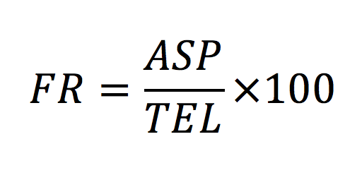
See what happened there? Multiplying by 100 gets rid of two of those offending zeroes. Now are result for friction rate looks like this:
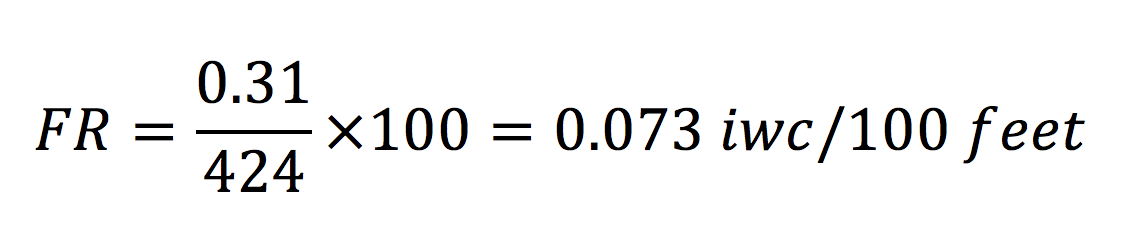
In this case, our friction rate is 0.073 iwc/100′. That’s the number we use to size the ducts.
How to think about friction rate
The big problem a lot of people have with friction rate is they don’t actually calculate it. They assume it. And the number they usually assume is 0.1 iwc/100′. That’s close to what I calculated above, but if you use 0.1 instead of 0.073, your ducts will be undersized. Do you know why they’ll be undersized?
When you calculate the friction rate for a particular design, you’re finding out how much pressure drop you can get away with for each 100 feet of effective length of your duct system. If the number is higher, you can use smaller, more restrictive ducts. If the number is lower, you have to use larger ducts.
Make sense? Maybe not. We’re used to thinking of friction as something that we want to decrease, right? Now I’m telling you that a high friction rate allows us to use smaller ducts. It seems counterintuitive. But it’s not. I think the mental hangup here is because of the word “friction.” Think of it in terms of pressure drop allowed and it makes more sense.
Another way to think of it is in terms of the two numbers that went into the calculation. We want available static pressure to be as high as possible and total effective length to be as low as possible. Higher ASP (good) and lower TEL (good) both make the FR go higher (good).
If you’re new to this concept, you may have to chew on that for a while before it makes sense. But it will.
In the next article, we’ll see how friction rate translates to duct sizes and how a duct sizing calculator works.
Buy the ACCA Manuals on Amazon*


Other articles in the Duct Design series:
The Basic Principles of Duct Design, Part 1
Duct Design 2 — Available Static Pressure
Duct Design 3 — Total Effective Length
Duct Design 5 — Sizing the Ducts
Related Articles
The 2 Primary Causes of Reduced Air Flow in Ducts
How to Install Flex Duct Properly
The Science of Sag – Flex Duct and Air Flow
The Secret to Moving Air Efficiently through Your Duct System
* These are Amazon Associate links. You pay the same price you would pay normally, but Energy Vanguard makes a small commission if you buy after using the link.
This Post Has 4 Comments
Comments are closed.

“And poets use poetic
“And poets use poetic notation, which really doesn’t make any sense but it’ll make you cry tears of joy.”
Hey Allison, I thought that is called poetic license :).
In my endearing, self-deprecating fashion, let me once again submit a query that broadcasts my ignorance.
My limited understanding of air delivery in duct systems recalls there are different cfm requirements between the heating and cooling season. How does that fun fact play into calculations you have so eloquently described?
The duct system is the
The duct system is the travesty of the HVAC industry. Unfortunately, our inspectors don’t understand or don’t care as the majority of the systems installed in the MidSouth don’t take the duct into consideration at all. It’s a nightmare out there. Actually, it’s appalling to see what they are doing to their customers. Municipalities should make it law that every home should have a duct design before any system is put in.
Thank you for posting such
Thank you for posting such great and informative articles. The definition of FR based on ASP and TEL is very helpful for duct sizing. Is there any reference for this equation?
When the calculation of
When the calculation of Friction for a transition, using Ao/A1 ( area in and area out) then using the ashrae table SR-1 for transitions, or should we use velocity pressure in and out for friction,